Wall Rebar: settings and bar quantities
Complete 86-field reference with options and effects · Actual Revit model and generated results.
Use this with the Wall Rebar walkthrough. Open 01-Thep-vach-Revit-2024.rvt from the practice ZIP, then Save As. In a wall mesh, spacing normally controls the number of distributed bars; boundary bars also have a direct count field.
Choose the override scope first
Values inherit in this order: standard profile → layout template → project → core → storey group → branch → storey → zone. The most specific value wins. The right-panel breadcrumb shows the current scope. ○ means inherited; ● ↩ means a local override, and ↩ removes it.
| Desired change | Select | Effect |
|---|---|---|
| Project baseline | Detailing standard… and apply the profile to the project | Used where no narrower override exists. |
| Whole core or several levels | Core or Storey group | Descendant branches/storeys inherit it unless overridden. |
| One wall branch | Branch | Only this branch and its inheriting levels. |
| One level | Storey or a storey-table cell | Only the selected branch and storey. |
| A wall end, opening edge, or joint | Zone on the plan | Only that selected area. |
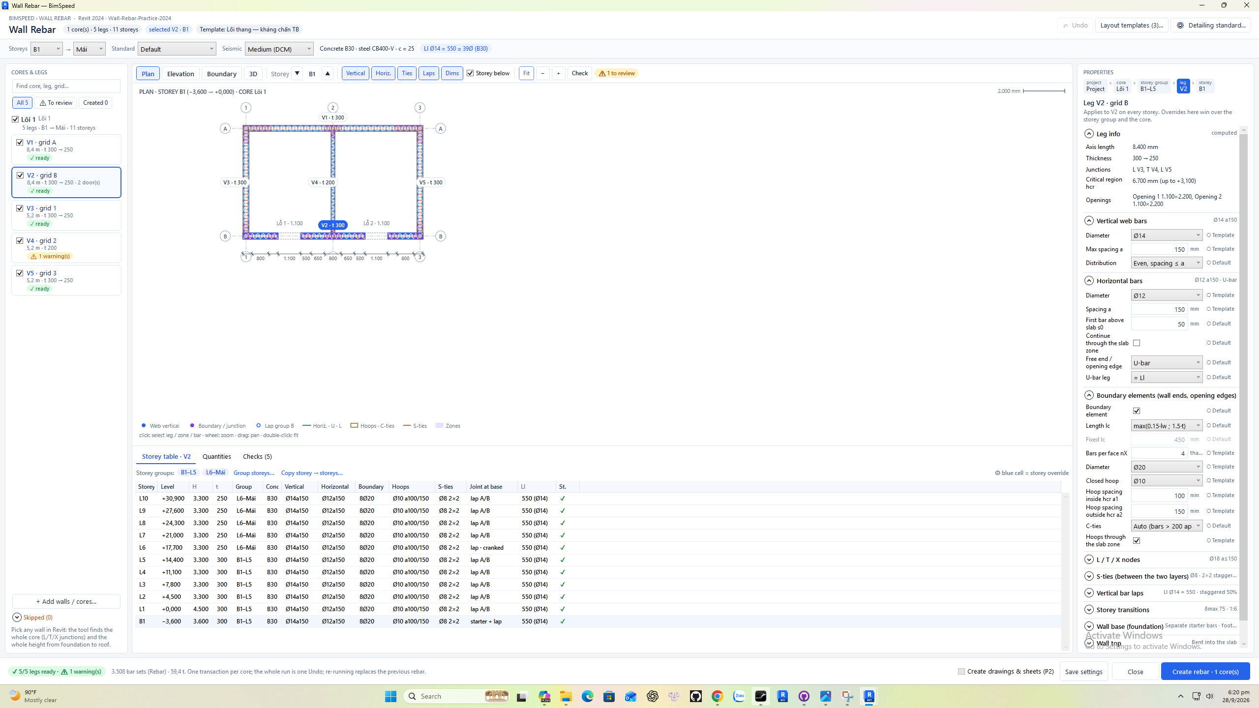
① core/branch selection; ② preview tabs; ③ scope breadcrumb and editable fields; ④ double-click a storey-table cell for one story; ⑤ Create rebar; ⑥ story range and standard.
Increase, decrease, and revise bars
| Case | What to edit | Verify |
|---|---|---|
| More vertical web bars | Vertical web bars → Maximum spacing a, e.g. 200 → 150 mm. | Smaller spacing normally creates more bars. Inspect Plan and Statistics; actual count depends on branch length and distribution mode. |
| Fewer vertical web bars | Increase a, e.g. 150 → 200 mm; check Distribution. | Re-run Check for spacing, ratio, and clearance findings. |
| More/fewer horizontal rows | At Storey or Branch, decrease/increase Horizontal bars → Spacing a. | Inspect Elevation, first-row offset s0, and whether bars pass through the slab. |
| Change diameter only | Vertical web bars → Diameter or Horizontal bars → Diameter. | Recheck lap/anchorage length, clearance, and mass; diameter changes do not inherently change bar count. |
| More/fewer boundary bars | Select a boundary Zone → Bars per face nX and diameter. | Inspect the boundary section; this does not change the web mesh count. |
| More/fewer boundary hoops | Lower/raise a1 in hcr / a2 outside hcr. | Inspect Plan, Elevation, 3D, and hoop-spacing warnings. |
| More/fewer S-ties | Under S-ties, reduce/increase the number of vertical/horizontal bars between ties. | Check the tie layer and TIE_DENSITY. |
| Revise L/T/X joints | Select the joint Zone, edit diameter/maximum spacing; joint extension belongs to Core. | Inspect joint bars and anchorage warnings. |
| Different reinforcement by floor | Select a Storey group or edit Vertical / Horizontal / Boundary / Hoops / S-ties in the storey table, e.g. Ø16a150 → Ø14a200. | The edited cell becomes an override; inspect transitions and starter bars at the floor. |
| Copy a floor's arrangement | Copy storey → other storeys…, then select target storeys and one branch/whole core. | Read each target row before creating. |
| Change lap length/location | Vertical laps → Ll, position, e0, staggering, lap type. | Check Elevation and 3D; manual Ll below the calculated value raises LAP_SHORT. |
| Change opening reinforcement | Select the opening edge Zone, then edit edge bars, diagonals, boundary region, and lintel bars/stirrups. | Check the opening in Plan/3D and opening warnings. |
| Revert an edit | Click ↩ on an overridden field, or Undo before creating. | The field returns to ○ and inherits its parent value. |
Exercise: on the F3 model, select storey group L6–Roof and branch V2. Change vertical maximum spacing from 150 to 200 mm and compare Plan/Statistics. Restore 150 mm; then select only L6 and change Ø14 to Ø16. Other storeys should stay unchanged. Click Check after every revision.
What each Detailing standard group controls
Open Detailing standard… at the top. Select a group at left, edit in the middle, read formulas/lap lengths at right, Save, then Apply to project. Units are mm unless a field states degrees, percent, bars, or a factor.
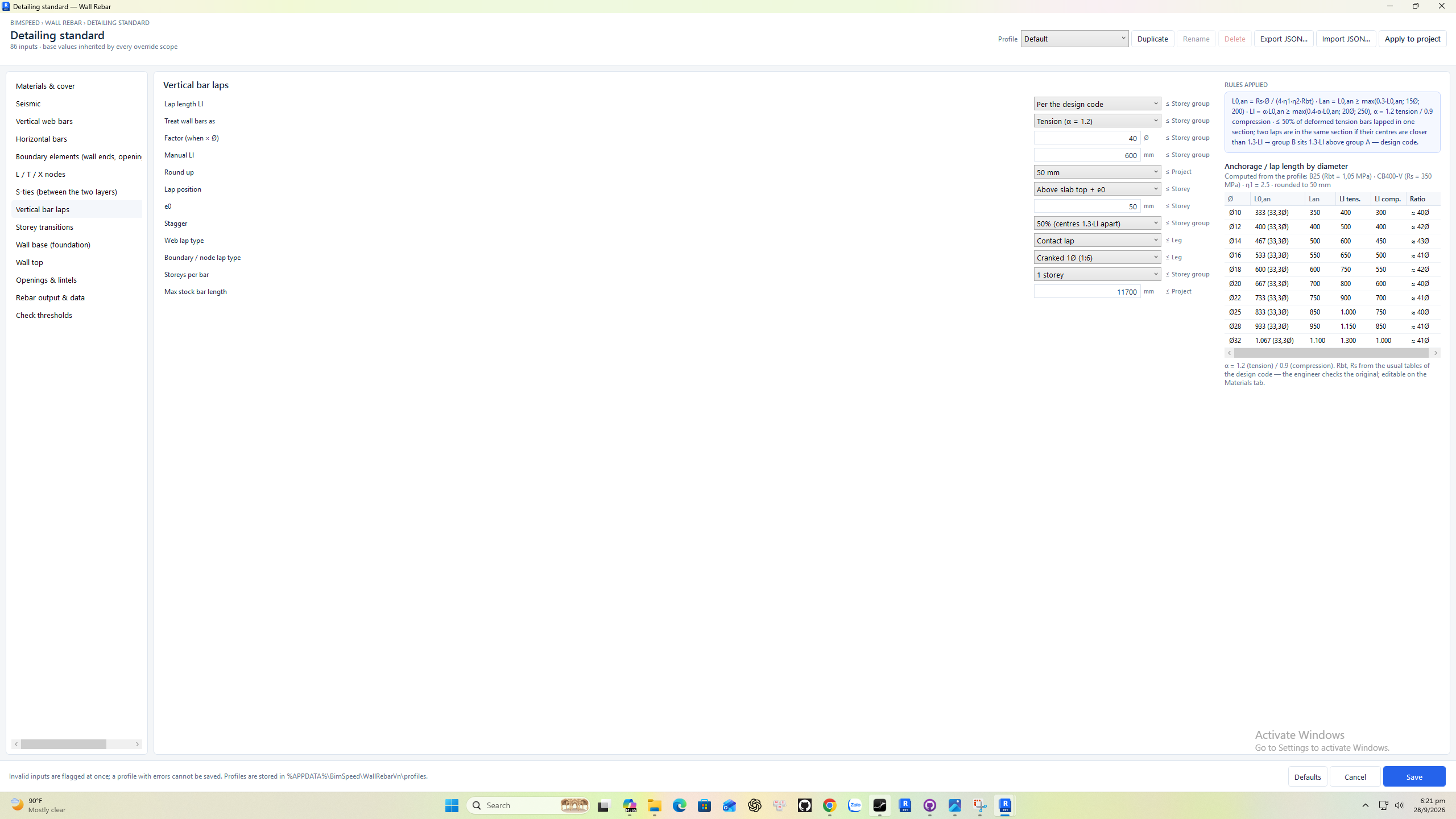
① groups; ② editable values; ③ rules and diameter-based anchorage/laps; ④ profile actions. Save is at the bottom-right. The screenshot shows the vertical-lap group.
| Group | Purpose |
|---|---|
| Materials & cover | Concrete/main and tie steel for anchorage and bar types; wall/slab/foundation cover positions bars; horizontal bars inside/outside vertical bars. |
| Seismic | Selects None/Low/Medium/High rules for critical regions and confinement; follow the engineer's design. |
| Vertical web bars | Diameter, maximum spacing, and even or end-remainder distribution. |
| Horizontal bars | Diameter, spacing, first-row offset, through-slab option, U/90° free ends, L-corner and T-joint treatment. |
| Boundary regions | Enable/disable, length formula/fixed/count, bars per face, diameter, hoop diameter and a1/a2, C-ties, through-slab hoops. |
| L/T/X joint regions | Joint-branch extension, bar diameter and maximum spacing. |
| S-ties | Diameter, bars between ties horizontally/vertically, stagger/grid pattern, hook angles. |
| Vertical laps | Ll from standard, diameter factor, or manual mm; tension/compression, rounding, location/e0, staggering, web/boundary type, storeys per bar, stock length. |
| Storey transitions | Maximum offset, bend slope, and anchorage leg when wall alignment/thickness changes. |
| Wall base | Separate/continuous foundation starter bars, foot length/direction, ties in foundation. |
| Wall top | Bent leg into slab, U-cap, or straight starter; leg direction. |
| Openings & lintels | Ignore-small-opening threshold, edge/diagonal bars, jamb boundary, lintel top/bottom bars and stirrups. |
| Output & information | Rebar Partition, level parameter, view colorization, solid 3D display; affects output rather than strength design. |
| Check thresholds | Fourteen limits including cover, clearance, thin wall, S-tie density, bend slope, T-joint anchorage, and opening trim. These change warnings, not the number of bars; override only at Project. |
Save and create again
- Save settings stores the plan in the model. Check does a trial Revit write and rolls it back. Resolve cover, clearance, short-lap, or missing-shape/bar-type errors.
- Create Rebar · N cores writes the bars. Compare the result table and Statistics by diameter, count, length, and mass; inspect the edited storey in Revit 3D.
- Create again after changes: unchanged sets retain their Rebar IDs; changed sets are updated; obsolete sets are removed. If tool-created bars were manually edited, the prompt means Yes = keep manual changes; No = overwrite from the current plan; Cancel = stop.
- If quantities did not change, check the scope, a narrower override, distribution mode, whether the core was ticked, and whether you ran Create again.
All numeric examples show UI operations only. The engineer must verify required steel area, cover, laps, anchorage, and detailing before issuing a model.