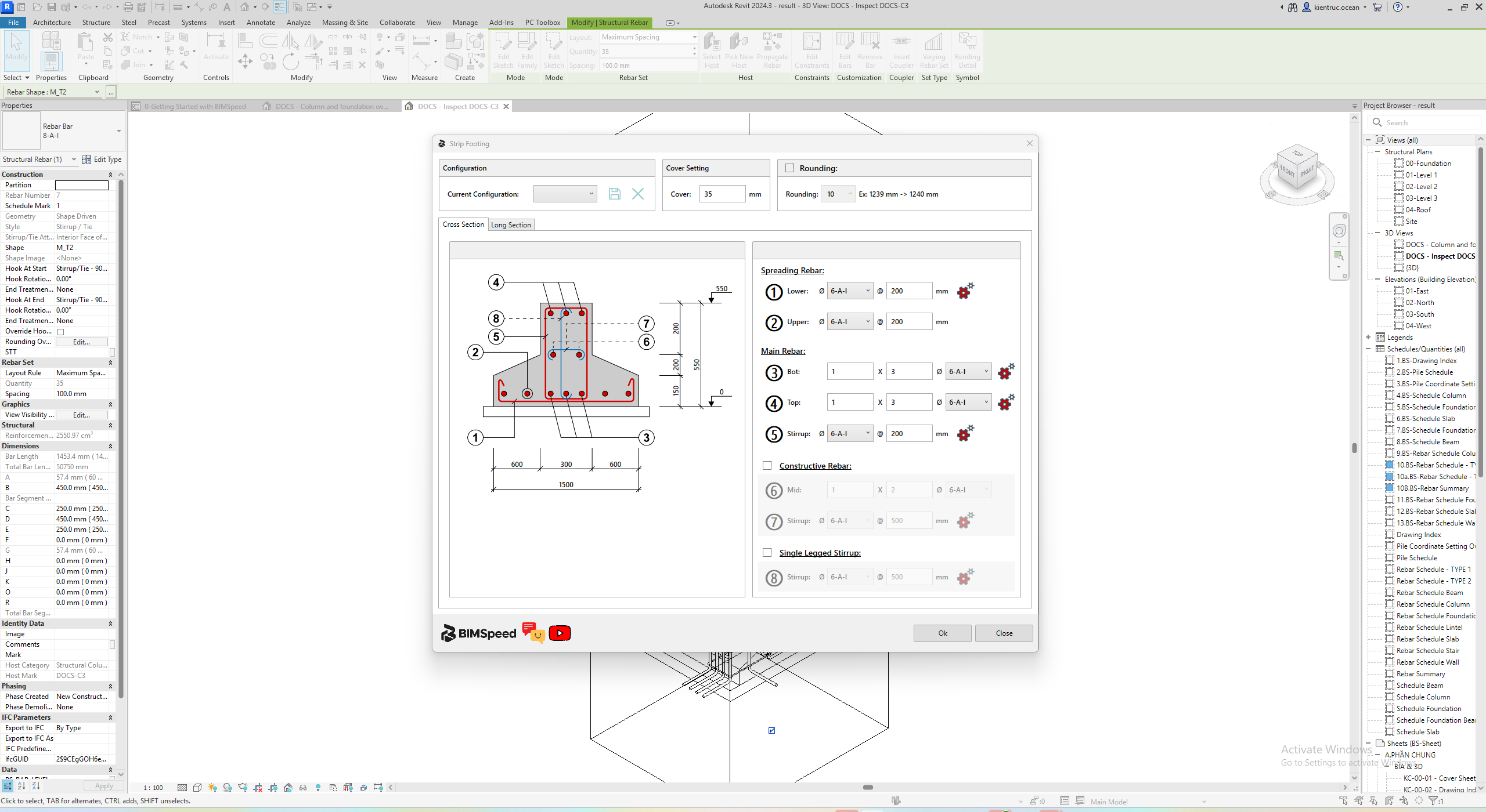
Strip Footing
Open BimSpeed.STR → Foundation → Strip Footing and select a compatible strip-footing family. The command can ask for two points limiting the processed segment; distinct points define its directed extent.
Workflow
- Save As. Check the selected FamilyInstance is accepted by the filter; an arbitrary Wall Foundation is not an equivalent host.
- Select the host. To limit the segment, accept the point-selection prompt and pick two points; otherwise the host length is used.
- Under Cross Section map numbers ①–⑧ to roles, set cover and open each required Hook Setting.
- Open Long Section and set reinforcement enable flags, length ratios, layers, counts and types for each region.
- Choose Ok. Retain any error messages. Inspect 3D and sections, count sets/bars by host and check zones/hooks before saving.
Scope, configurations and units
The command expects a structural-foundation FamilyInstance with a line-based LocationCurve; a Wall Foundation is not automatically equivalent. With two picked limits, check start-to-end direction because left/right zones follow the processing direction. After cancelling point picking, verify the recognized scope before continuing.
| Field / button | Units / options | Condition / scope | Effect and verification |
|---|---|---|---|
| Current Configuration | preset | selected footing or segment | Loads a saved configuration. Recheck Cross Section and Long Section; its name does not guarantee suitability for this geometry. |
| Save configuration (disk) | action | current settings | Opens a naming dialog; enter a distinct name and Save a reusable preset. This does not create bars or save the RVT. |
| Delete configuration (X) | action | selected preset | Removes the selected configuration, not generated bars. Check the selected name first. |
| Cover | mm | selected footing or segment | Cover for the cage; increasing it shrinks the bar region. Measure from the structural concrete face, not outer blinding geometry. |
| Rounding | toggle | selected footing or segment | Enables the tool’s length-rounding rule without changing host dimensions. Inspect actual bar lengths and hook legs. |
| Rounding multiple | mm | Rounding enabled | Choose the offered increment. Follow the UI rounding example; it does not mean adding that increment to every bar. |
| Cross Section / Long Section | navigation | window | Changes the displayed settings, not model bars. The other tab’s settings still belong to the configuration used by Ok. |
Cross Section: roles ①–⑤
Use the built-in diagram numbers to identify each controlled role. Do not add tie Quantity to the main-bar count. Diameter fields select model Rebar types; inspect actual diameters rather than their names alone.
| Field / button | Units / options | Condition / scope | Effect and verification |
|---|---|---|---|
| ① Lower spreading: Ø | bar type | selected footing or segment | Select this distribution layer’s type; it does not change main bars. Inspect the distribution set’s Type Properties. |
| ① Lower spreading: @ | mm | selected footing or segment | Pitch for this layer. Reduce 200→150 to densify and inspect actual set count/pitch rather than diagram lines. |
| ② Upper spreading: Ø | bar type | selected footing or segment | Select this distribution layer’s type; it does not change main bars. Inspect the distribution set’s Type Properties. |
| ② Upper spreading: @ | mm | selected footing or segment | Pitch for this layer. Reduce 200→150 to densify and inspect actual set count/pitch rather than diagram lines. |
| ③ Bottom main: Layers | layers | selected footing or segment | Number of vertical layers, not bars per layer. Inspect each layer’s elevation. |
| ③ Bottom main: Quantity | bars/layer | selected footing or segment | Bars per layer for this role. The nominal straight-bar total is Layers × Quantity; verify actual sets and segments. |
| ③ Bottom main: Ø | bar type | selected footing or segment | Independent top/bottom main-bar type. Changing diameter affects clearances and any diameter-based lengths in that branch. |
| ④ Top main: Layers | layers | selected footing or segment | Number of vertical layers, not bars per layer. Inspect each layer’s elevation. |
| ④ Top main: Quantity | bars/layer | selected footing or segment | Bars per layer for this role. The nominal straight-bar total is Layers × Quantity; verify actual sets and segments. |
| ④ Top main: Ø | bar type | selected footing or segment | Independent top/bottom main-bar type. Changing diameter affects clearances and any diameter-based lengths in that branch. |
| ⑤ Main stirrup: Ø | bar type | selected footing or segment | Main tie diameter, separate from main and distribution bars. Inspect Stirrup/Tie style and shape. |
| ⑤ Main stirrup: @ | mm | selected footing or segment | Main-window tie pitch; open its gear to inspect distribution mode and zone values before generation. |
Optional roles ⑥–⑧ and enabling conditions
Enable only the required roles. Middle/single-leg tie gears belong to dependent groups; enable the role before editing them. An opened Hook Setting dialog alone does not prove that role was generated.
| Field / button | Units / options | Condition / scope | Effect and verification |
|---|---|---|---|
| Constructive Rebar / Middle: enable | toggle | selected footing or segment | Enables middle bars and their ties; gray retained values when disabled are not output evidence. Verify actual model elements after Ok. |
| ⑥ Middle: Layers | layers | role enabled for child fields | Middle-bar layer count, not spacing or bars per layer. Verify actual model elements after Ok. |
| ⑥ Middle: Quantity | bars/layer | role enabled for child fields | Bars per middle layer; inspect position relative to top and bottom bars. Verify actual model elements after Ok. |
| ⑥ Middle: Ø | bar type | role enabled for child fields | Middle-bar type, independent of top/bottom main types. Verify actual model elements after Ok. |
| ⑦ Middle stirrup: Ø | bar type | role enabled for child fields | Tie type for middle bars; use its gear to inspect hooks independently. Verify actual model elements after Ok. |
| ⑦ Middle stirrup: @ | mm | role enabled for child fields | Middle-tie pitch; it does not automatically follow main tie ⑤. Verify actual model elements after Ok. |
| Single Legged Stirrup: enable | toggle | selected footing or segment | Enables single-legged ties; inspect their connection to the intended longitudinal bars. Verify actual model elements after Ok. |
| ⑧ Single leg: Ø | bar type | role enabled for child fields | Single-leg tie type; do not substitute a similarly named longitudinal type. Verify actual model elements after Ok. |
| ⑧ Single leg: @ | mm | role enabled for child fields | Pitch for single-legged ties; inspect count and hooks in section/3D. Verify actual model elements after Ok. |
Long Section: reinforcement regions and quantities
Left/right follows the tool’s processing diagram. Recheck reversed hosts or reversed picked limits. Change one divisor while keeping layers/diameter fixed to isolate the length effect before changing bar quantity.
| Field / button | Units / options | Condition / scope | Effect and verification |
|---|---|---|---|
| Add Reinforced Rebars in the length direction | toggle | selected footing or segment | Enables longitudinal reinforcement in Long Section. Inspect both end regions after enabling. |
| Bottom left: L / | divisor | longitudinal reinforcement enabled | Divisor of processed length L. L/4 is not 4 mm; a larger divisor shortens that region. Inspect the region along the host direction. |
| Bottom right: L / | divisor | longitudinal reinforcement enabled | Divisor of processed length L. L/4 is not 4 mm; a larger divisor shortens that region. Inspect the region along the host direction. |
| Top left: L / | divisor | longitudinal reinforcement enabled | Divisor of processed length L. L/4 is not 4 mm; a larger divisor shortens that region. Inspect the region along the host direction. |
| Top right: L / | divisor | longitudinal reinforcement enabled | Divisor of processed length L. L/4 is not 4 mm; a larger divisor shortens that region. Inspect the region along the host direction. |
| Bottom left: Layers | layers | longitudinal reinforcement enabled | Layer count for this region, independent of L/n length. Count it separately in the model. |
| Bottom left: Quantity | bars/layer | longitudinal reinforcement enabled | Bars per layer in the region; inspect their termination positions. Count it separately in the model. |
| Bottom left: Ø | bar type | longitudinal reinforcement enabled | Bar type for this region; left/right/top can differ. Count it separately in the model. |
| Bottom right: Layers | layers | longitudinal reinforcement enabled | Layer count for this region, independent of L/n length. Count it separately in the model. |
| Bottom right: Quantity | bars/layer | longitudinal reinforcement enabled | Bars per layer in the region; inspect their termination positions. Count it separately in the model. |
| Bottom right: Ø | bar type | longitudinal reinforcement enabled | Bar type for this region; left/right/top can differ. Count it separately in the model. |
| Top: Layers | layers | longitudinal reinforcement enabled | Layer count for this region, independent of L/n length. Count it separately in the model. |
| Top: Quantity | bars/layer | longitudinal reinforcement enabled | Bars per layer in the region; inspect their termination positions. Count it separately in the model. |
| Top: Ø | bar type | longitudinal reinforcement enabled | Bar type for this region; left/right/top can differ. Count it separately in the model. |
Main/distribution Hook Settings
The three gears open independent settings. Choose the shape before entering visible L1/L2 values; do not transfer top-bar hook directions to bottom bars. The child dialog’s Ok confirms settings only.
| Field / button | Units / options | Condition / scope | Effect and verification |
|---|---|---|---|
| Bottom main: Hook Type | BottomHook / BottomStraight | role’s gear dialog | Choose a bent or straight shape icon. This controls role geometry, rather than the Revit stirrup-hook type dropdown. |
| Bottom main: L1 | mm | bent shape selected | Length of the illustrated red leg, not total bar length. Inspect the actual shape after Ok. |
| Top main: Hook Type | TopHook / TopStraight | role’s gear dialog | Choose a bent or straight shape icon. This controls role geometry, rather than the Revit stirrup-hook type dropdown. |
| Top main: L1 | mm | bent shape selected | Length of the illustrated red leg, not total bar length. Inspect the actual shape after Ok. |
| Lower spreading: Hook Type | BottomHook / BottomStraight | role’s gear dialog | Choose a bent or straight shape icon. This controls role geometry, rather than the Revit stirrup-hook type dropdown. |
| Lower spreading: L1 | mm | bent shape selected | Length of the illustrated red leg, not total bar length. Inspect the actual shape after Ok. |
| Lower spreading: L2 | mm | eccentric/shape branch displaying L2 | Second lower-distribution hook leg, which may differ from L1. Do not force-edit a hidden L2 field. |
| Hook Setting: Ok | action | open hook dialog | Returns settings to the main window; it does not generate bars until the main Strip Footing Ok. |
Stirrup Setting: separate configurations for ⑤, ⑦ and ⑧
Main, middle and single-leg ties use the same dialog design with independent values. After each Ok, verify which role you edited. Switching Uniform/Varying changes visible regions and dependent fields; stored hidden values do not establish the generated layout.
| Field / button | Units / options | Condition / scope | Effect and verification |
|---|---|---|---|
| Hook Type | Revit hook type | all modes | Loaded Revit tie hook; inspect angle and start/end orientation after generation. |
| Distribution Type | Uniform / Varying | all modes | Uniform distributes evenly; Varying exposes left/middle/right zones. These are not batch-column A/B/C modes. |
| Start Offset | mm | all modes | Offset of the first tie from the processed start, not an L/n divisor. Measure it in the longitudinal view. |
| End Offset | mm | all modes | Last-tie offset at the other end; it does not change host length. |
| Left: L / | divisor | Varying | Defines the left zone as L/n. Inspect the pitch-transition boundary before changing spacing. |
| Right: L / | divisor | Varying | Defines the right zone independently; the remainder forms the middle zone. |
| Left Spacing | mm | Varying | Left-zone pitch; reducing it densifies only the left zone. |
| Spacing / Middle Spacing | mm | Uniform or middle Varying zone | Uniform pitch or middle-zone pitch according to the active mode; read the displayed label/diagram. |
| Right Spacing | mm | Varying | Right-zone pitch; it does not automatically follow Left Spacing. |
| Stirrup Setting: Ok | action | open dialog | Confirms this tie configuration. Recheck the main diagram and pitches; this is not element generation. |
Generate, inspect and save
Generate on a copy and count by host and role. After Ok, select a set in each pitch zone and read Quantity/Spacing/Type, then inspect hooks and cover in section. Save and reopen a result copy to confirm persistence; saving a preset does not do this.
| Field / button | Units / options | Condition / scope | Effect and verification |
|---|---|---|---|
| Main window: Ok | action | selected footing or segment | Generates from both tabs and confirmed dialogs. On error/rollback, verify no partial bars remain; do not treat the preview as output. |
| Close | action | window | Closes the window; it does not replace Save RVT. Displayed settings do not establish generated Rebar. |
| Update | version-dependent | not present in the captured create flow | This button was not verified in the create workflow. Update Strip Footing Drawing is a separate drawing command, not a cage regeneration button. |
Checking changes and direction
Test lower mesh pitch 200 → 150 mm, then 150 → 200 on another copy; count that role separately. For a two-point segment, compare reinforced length with full host length. L/4 is a ratio, not millimetres. Strip Footing Drawing.
Map of the actual window
This English UI capture uses an educational strip footing with a line-based LocationCurve. The tool's built-in ①–⑧ numbers connect input roles to the illustration; they are not Rebar IDs. Constructive Rebar and Single Legged are disabled, so their gray child fields are intentional. The capture verifies controls, not generated strip-footing bars.
1: configuration, cover and rounding; 2: Cross Section/Long Section navigation; 3: distribution and main bars; 4: enable an optional role before editing its children; 5: Ok generates, Close exits.