Shear Wall
The images identify controls in the exercised build. Read the version and run limitations below before applying the workflow. Proposed exercises are not verified results; no accepted result-model download is available for this tool.
Shear Wall opens a section editor for one Basic Wall or column. Use BimSpeed.STR → Wall → Shear Wall. The host must accept Rebar: enable Structural and use concrete. Curtain and stacked walls are rejected. This is separate from Wall Rebar TCVN.
- Pick the host. Choose a two-point length only when restricting the designed segment; the points must differ. Select relevant intersecting walls at the adjacent-wall prompt, then Finish; cancel that selection for an isolated-wall exercise.
- Verify thickness, length, heights and the upper beam. Review Geometry, Longitudinal bars, Stirrups and Settings.
- Select a segment on the canvas before editing its distribution. Left end, middle and right end can use different counts and diameters. Read the displayed values again after changing segments.
- Design ties on the section. Hook ties use a selected bar; closed ties use pairs. Selecting an existing configuration again may remove it. Review the diagram before OK.
- OK proceeds to native Rebar creation. The canvas and dialog elevation remain proposals until Revit elements are inspected.
Deliberate changes
Increase and then decrease the count in the same segment and group, inspecting its canvas distribution each time. Changing diameter does not mean changing count. A proposed spacing exercise is 200 → 150 mm; after creation inspect actual spacing and Quantity for that set. A set quantity is not the whole-wall count. Example values are not a design recommendation.
Save and repeat
Creation stores design data on the host. Closing the editor does not create bars or save the RVT. Keep a copy before repeating on reinforced hosts; replacement/deletion behavior has not been runtime verified for every case. Inspect the native model in a Fine 3D view, enable Unobscured where needed, and check wall ends and laps. Select representative Rebar to read diameter, Quantity, Spacing and host. Save a separate RVT and reopen the prepared view.
One host does not establish multi-storey behavior. Use Shear Wall Multi Segments for a shared design across segments.
Settings
| Control | Unit / choices | Effect and verification |
|---|---|---|
| Thickness / length / height / beam / upper segment | mm | Read from the host; compare with native Properties and section geometry. |
| Cover | mm | Moves bars inward; inspect concrete face to bar surface. |
| Lap at base / between floors | Choice | Changes lap location; inspect bar end elevations. |
| Base length / top length | mm | Controls the illustrated end regions, not total host height. |
| Calculate by diameter | On/off | Uses multipliers × diameter. This UI does not expose every alternative fixed-length control; do not assume all mm alternatives are available. |
| Between-lap distance / lap length | × diameter | Changes staggering and overlap; diameter changes effective lengths. |
| Uniform / concentrated ends | Distribution | Uses a uniform group or separate left/middle/right groups. |
| Left / right zone length | mm | Sets boundary-zone limits; inspect both ends and remaining middle length. |
| X / Y counts and diameter | Integer; mm | Separate values for the active uniform or end/middle group. Avoid double-counting corner bars. |
| Left / right strengthening | On/off | Adds the inner Y-row at that boundary-to-middle interface; clearing it does not remove all X-bars from the boundary zone. Verify host direction. |
| Support bars: top / bottom / left / right | Counts | Edits groups at the selected support; inspect the section. |
| Roof bars; Lb | On/off; mm | Top-end treatment and bent length; inspect actual top bar shape. |
| Foundation bars / ties / H / L / foot shape | On/off; mm; shape | Foundation-end choices; verify anchorage geometry inside the actual footing. |
| Tie type | Closed / hook / custom | Changes the canvas bar-picking operation and resulting tie shape. |
| Main tie: diameter / spacing / shape / A / B / lap | mm; shape | Separate diameter, pitch and shape dimensions; inspect the outline and lap leg. |
| End tie: diameter / spacing / shape / A / B / lap | mm; shape | Applies to the end region, separately from middle ties. |
| Additional tie diameter / spacing | mm | Additional-group diameter and vertical repetition; inspect that set separately. |
| Start / Step / Range; Auto generate | Indices; integers | Defines which longitudinal bars are linked; review the canvas after automatic generation. |
| Drawing; view type / template / scale | On/off; type; 1:n | Controls drawing output. Templates can hide bars; scale does not resize model geometry. |
| Longitudinal / tie tags; dimension type | Family type | Requires usable types; inspect generated tags and dimensions. |
| Sheet; number / name / title block | On/off; text; family | Controls sheet output; verify unique sheet number and viewports. |
| Pages / OK / Close | Buttons | Pages switch the editor; OK accepts the proposal; Close exits. |
Revit and the input host
This maximized native Revit view isolates the input wall on a project copy. It is not a reinforcement count or newly generated output. The later editor images explain the controls.
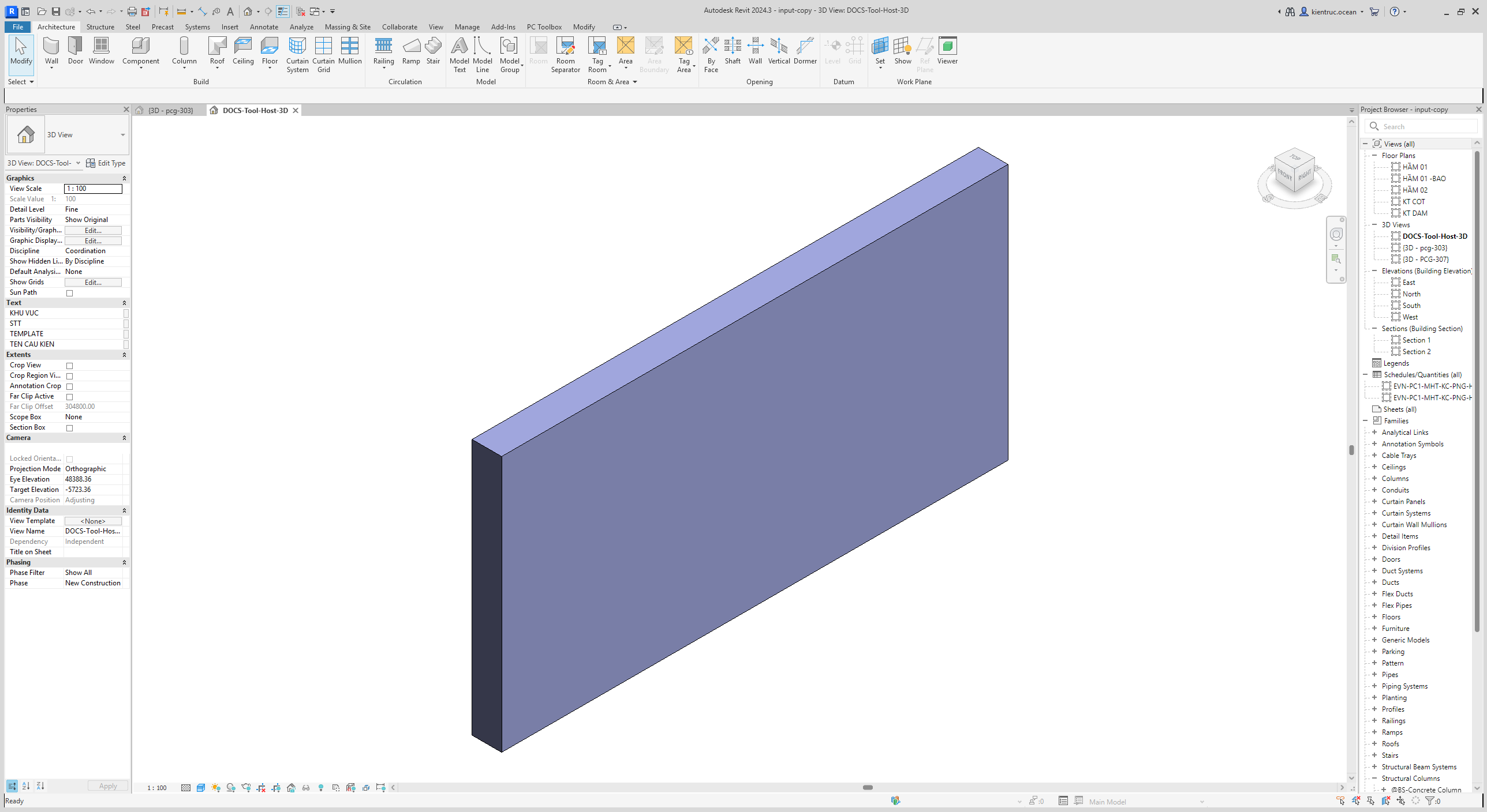
- The existing wall is isolated for geometry inspection; it does not replace the building with a fixture.
- Properties belongs to the view, not a Rebar element. Revit is English; project-defined level/parameter names may remain Vietnamese.
Read the four editor pages
The Shear Wall editor below was opened for one native host in Revit 2024. The section proposal is not committed Rebar.
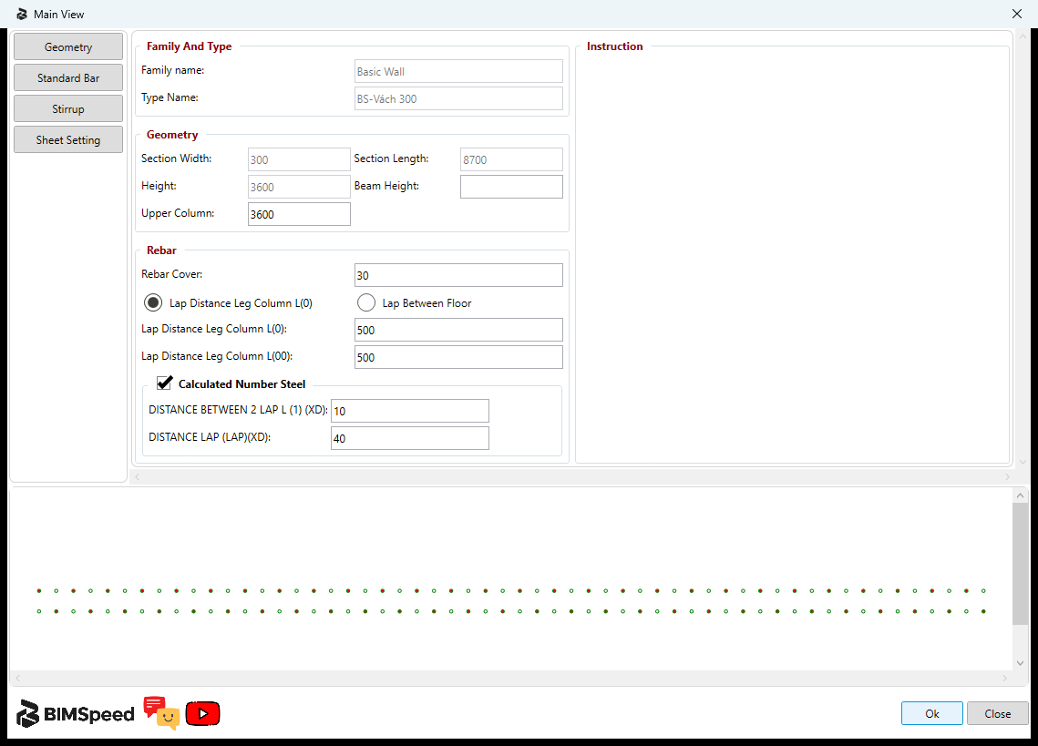
- Switch Geometry, Standard Bar, Stirrup and Sheet Setting; these are tool pages, not Revit views.
- Read-only family/type and section dimensions come from the host. The recognized section length may differ from its location curve.
- Cover, lap placement and L(0)/L(00) act on longitudinal bar ends; inspect both elevations.
- The diameter-based lap group has separate stagger and lap multipliers. Changing bar diameter can change the resulting length.
- OK accepts a design for command execution; Close leaves it. This image demonstrates UI only.
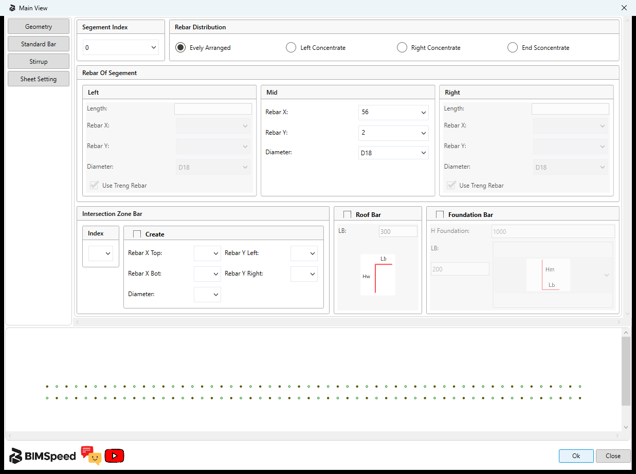
- Select a segment index and its even/left/right/both-ends distribution before editing counts.
- Each active left/middle/right zone has its own X, Y and diameter; grey zones are inactive. Check X along wall length and Y through thickness.
- The intersection-zone index scopes the four face counts and diameter to one support; Create here is a group toggle, not the main OK button.
- Roof and foundation options are mutually exclusive: enabling one clears the other. Their Lb, height and foot-shape fields apply to the selected branch. Confirm the actual supporting geometry.
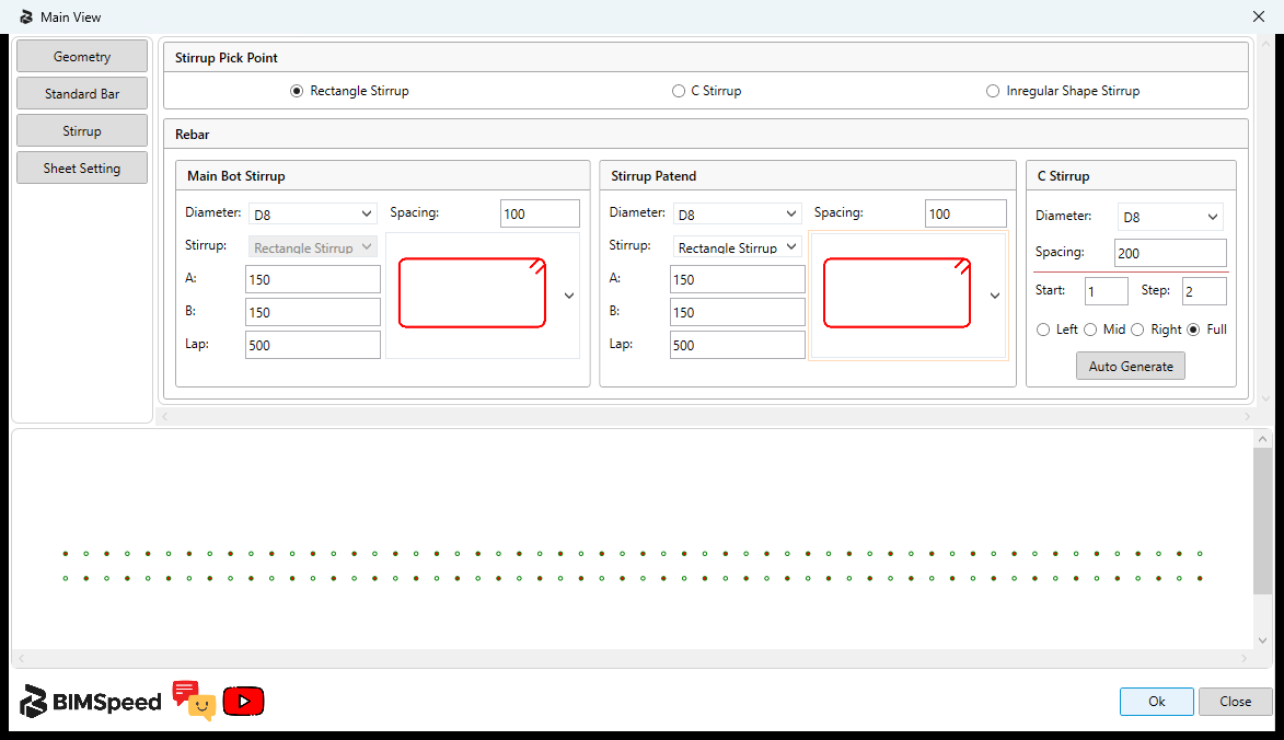
- Choose rectangular, C or irregular ties before picking in the section proposal.
- Lower and patterned tie groups have independent diameter, pitch and shape-related A/B/Lap values.
- C-tie diameter, pitch, start, index step and left/middle/right/all scope control Auto Generate. Review the proposal before main OK.
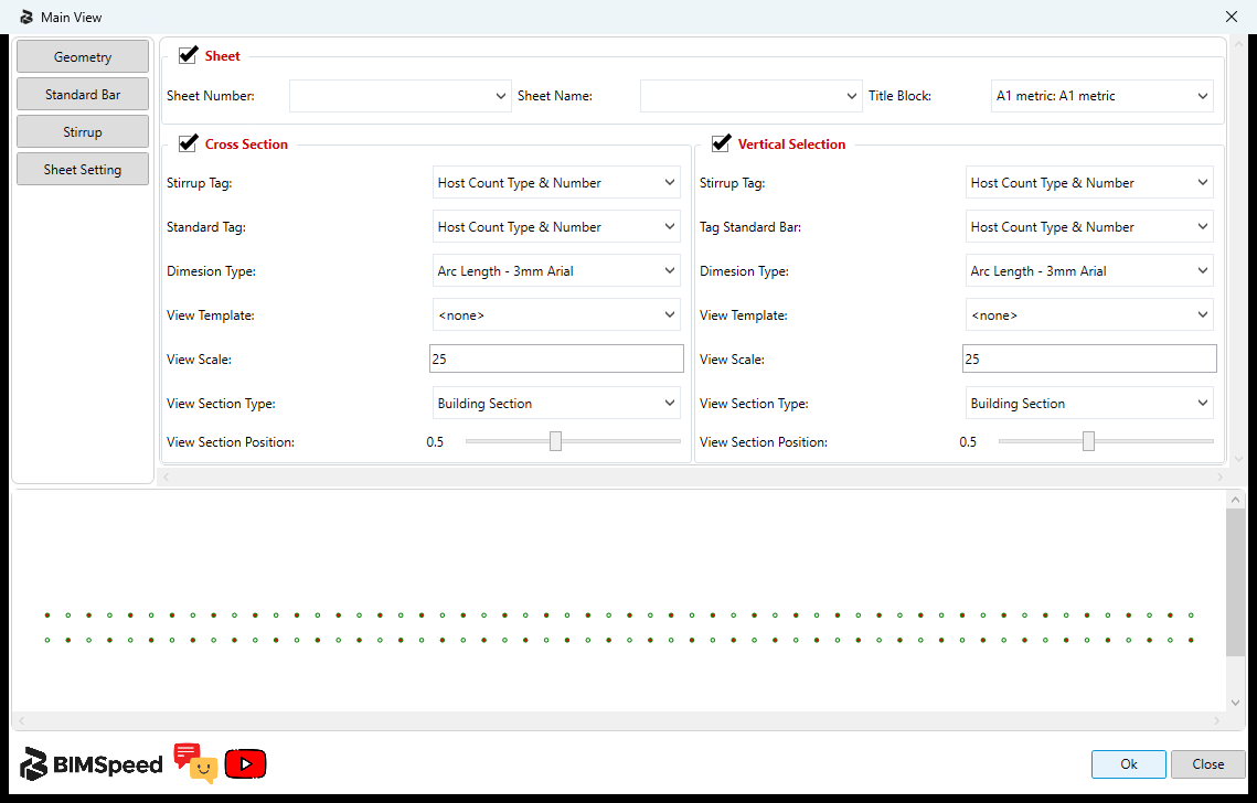
- Sheet additionally needs a number/name and titleblock available in the project.
- Cross Section has its own tie/main tags, dimension style, template, scale denominator, view type and cut position.
- Vertical Section has a separate set of those inputs. The scale changes drawing presentation, not reinforcement.
Deliberate changes
Increase then decrease the middle-zone X count while keeping Y/diameter fixed. Check the selected segment, then its native host quantity after creation. Switch to left-concentrated bars and check that right-zone controls remain inactive. Enable roof/foundation ends only for the appropriate storey. Changing the longitudinal view scale should affect that view, not bar geometry. These are verification exercises, not accepted generation runs.
Educational R24 wall input supports learning the single-host editor; it is neither multi-segment nor generated output.
Selecting an existing sheet number loads that sheet name and locks related sheet/titleblock inputs; a new number creates a new sheet. Check the Browser so views are not placed on an unintended sheet. For reinforcement only, turn off both section groups and Sheet before OK, then check the Browser. Use Treng Rebar belongs to its individual boundary zone; recheck that zone when toggling it.
Enabled editor branches
These are proposals on an existing project wall, not generated Rebar.
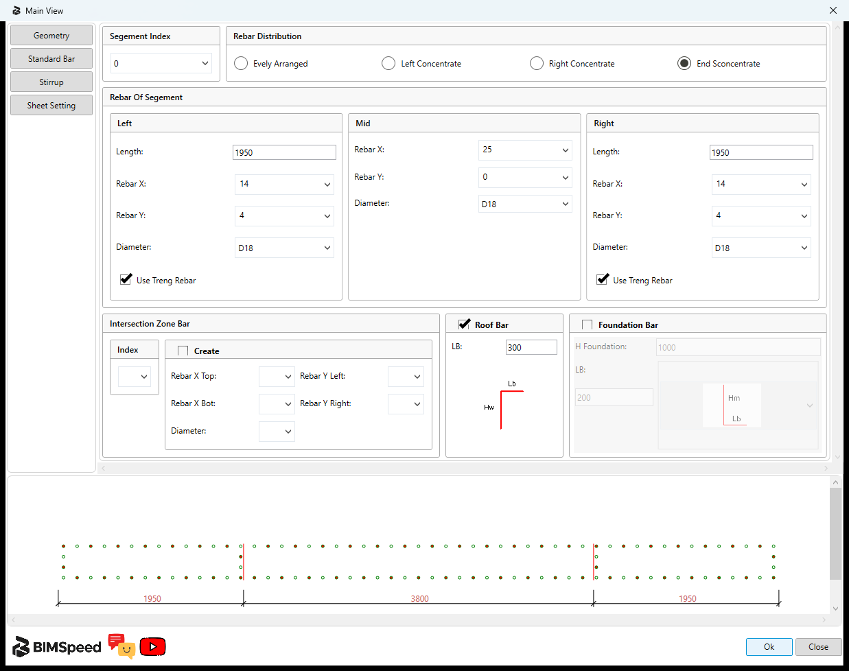
- End concentration activates the boundary regions.
- Left/middle/right and Use Treng have separate scopes; inspect the inner Y-row at each boundary.
- Roof Bar and Lb apply only to the active roof branch.
- Enabling Foundation Bar clears Roof Bar; its height/Lb/foot shape belong to that branch. The two pictures show alternative UI states, not two creation runs.
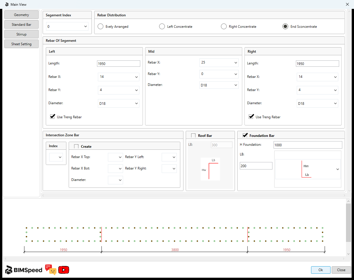
- End concentration activates the boundary regions.
- Left/middle/right and Use Treng have separate scopes; inspect the inner Y-row at each boundary.
- Roof Bar and Lb apply only to the active roof branch.
- Enabling Foundation Bar clears Roof Bar; its height/Lb/foot shape belong to that branch. The two pictures show alternative UI states, not two creation runs.
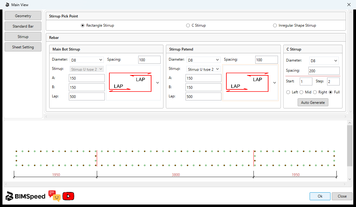
- Lower ties have their own diameter, pitch and A/B/lap inputs.
- The patterned group selects its own U form; read the Lap End limitation for the reviewed version.
- C-ties use separate diameter/pitch and Start/Step/scope. Auto Generate edits the proposal, not native model elements.
Requirement for model creation
The exercised Revit 2024 Release build displayed You are not logged in! during its command permission check and cancelled before creation. An open editor does not establish sign-in or creation permission. Use the normal BIMSpeed sign-in flow and check access to the exact command and Revit version before running on a copy. No generated, saved and reopened result has been verified for this command; its preview is not accepted output evidence.
Check the end-zone tie lap separately
Lap Main and Lap End are lengths in mm, not tie pitch. In the reviewed creation branch, end-zone U forms use Lap Main although the editor exposes and saves Lap End. A separate Lap End effect has not been verified in native output for the captured build; changing that field does not establish a changed end-zone lap. Inspect each role's actual shape and length in the intended version.
Use Treng and Auto Generate have different scopes
The left/right Use Treng Rebar toggles add the inner Y-row at that boundary-to-middle interface. X-bars on the two faces and the outer end row follow their separate distribution/support rules; clearing the toggle does not remove the entire boundary zone. Select the segment and compare that inner interface one side at a time.
Auto Generate C-ties operates on the selected segment. Start is a zero-based bar-list index: 0 selects the first bar and 1 the second. Step is an index increment, not mm; values below 1 are treated as 1. Left/Middle/Right/All scope regions within that segment, not the entire storey/project. The tool removes matching C-tie proposal items in the chosen region and rebuilds them, so it does not guarantee preservation of manually placed C-ties there. Review the canvas before OK; this proposal operation does not itself create/delete native model Rebar.