Formwork — Quantities and Scope
English Revit 2027.3 demonstration. Verification: Beam quantity output verified. Other category and linked-model combinations are settings demonstrations.
Video
Narration: Google Gemini Charon, professional English. The video retains the full Revit screen, briefly zooms on named controls, and includes timed English subtitles. Transcript · SRT.
1. Select the host and open Formwork
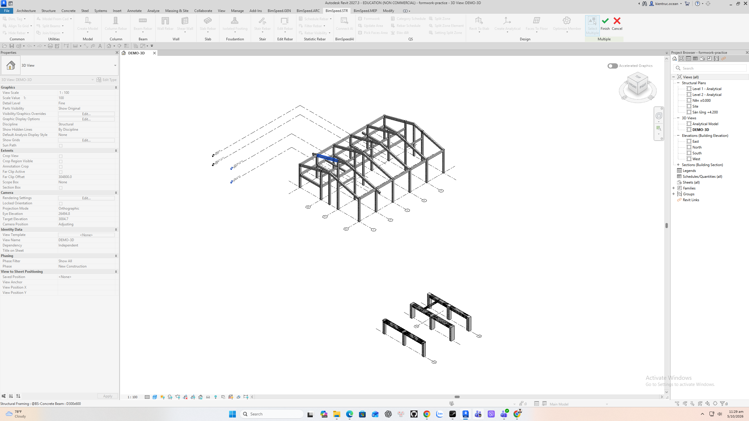
Select a native structural beam. Open BimSpeed dot S T R and choose Formwork. The practice beam is a D three hundred by six hundred millimeter member. The tool can also inspect the active view or a selection; confirm the scope before a larger project run.
2. Set surfaces and element scope
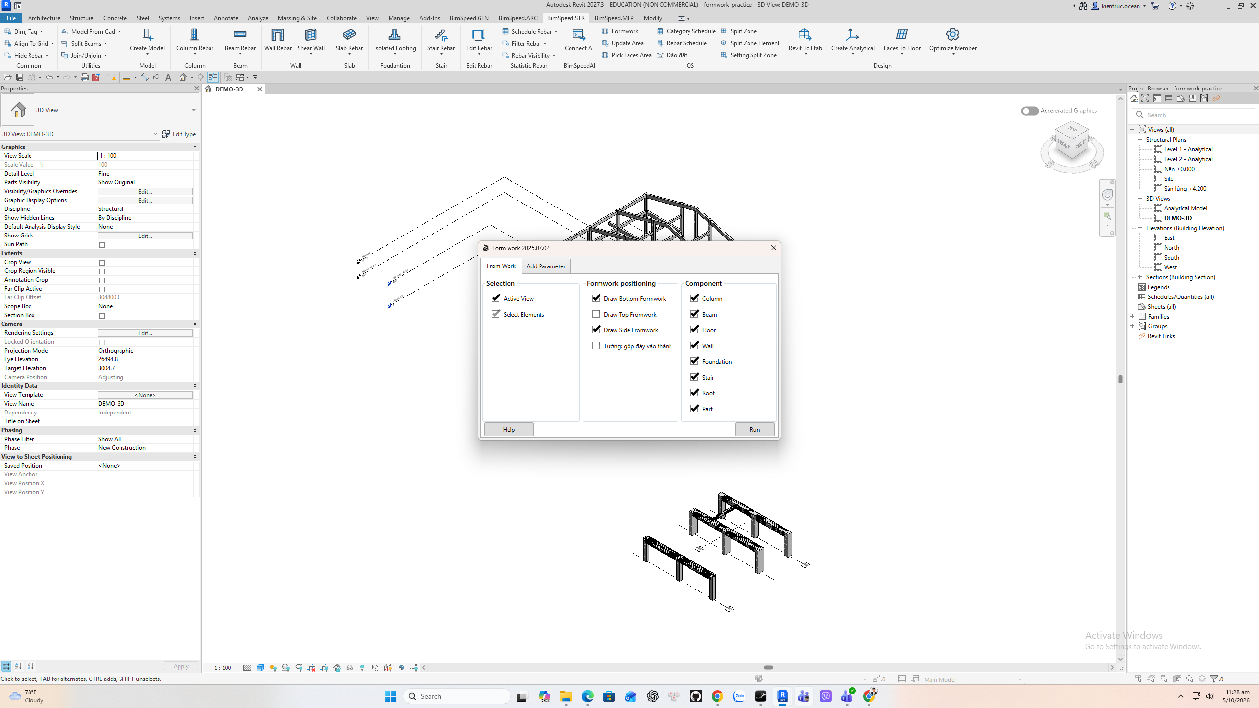
In From Work, choose Active View for the visible model or Select Elements for a bounded selection. Enable the Bottom, Top and Side surfaces required by your takeoff. Review the eight component category switches. In this installed build the Select Elements checkbox is bound to linked selection internally, so verify the selected set before relying on it for a whole project.
3. Map custom parameters
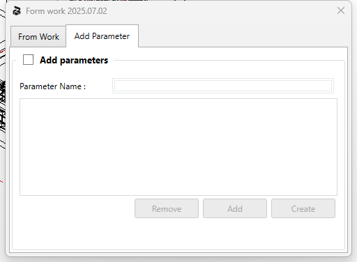
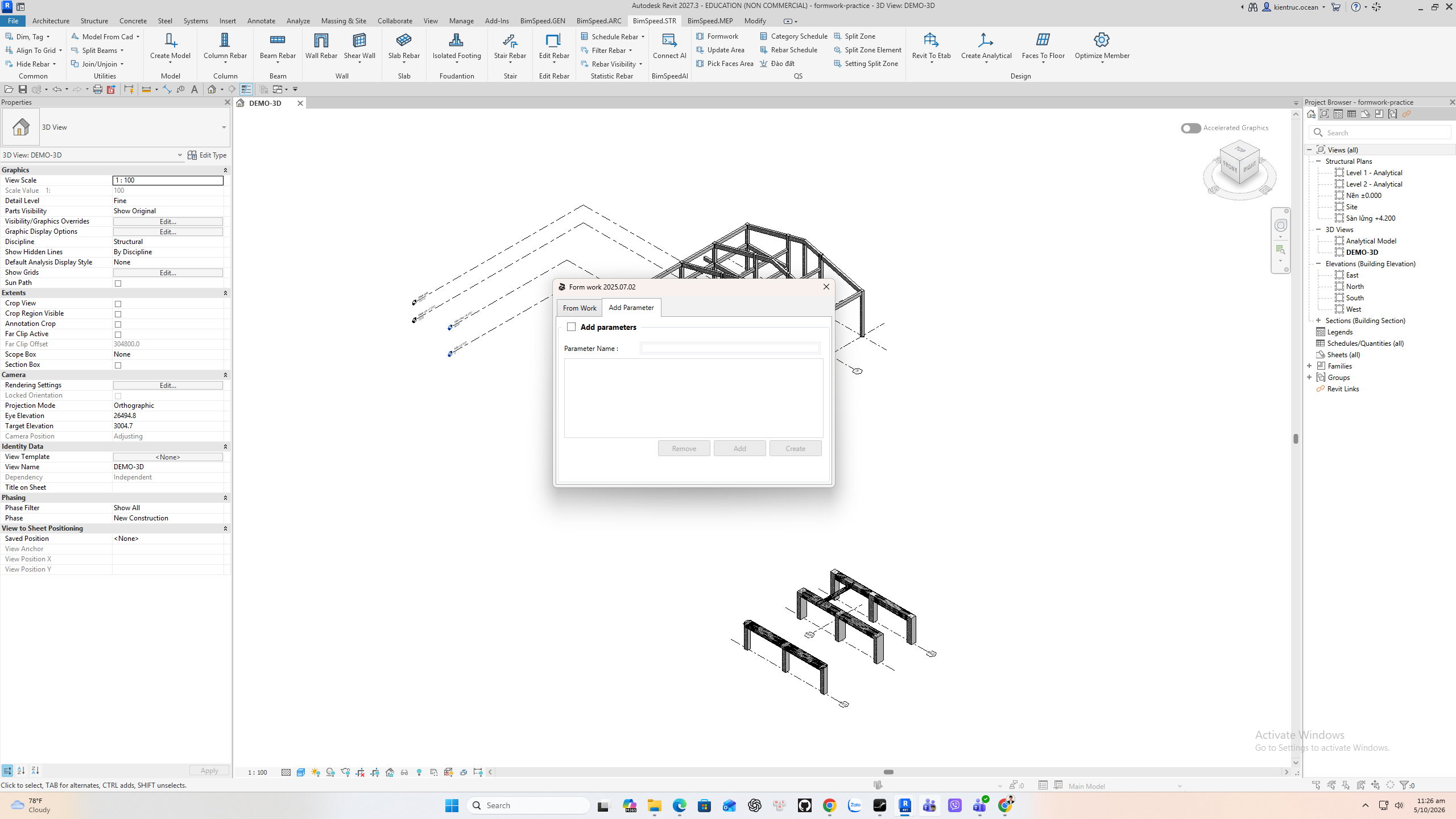
Use Add Parameter to create optional Text fields. Prepare the required Area instance parameters separately before scheduling host quantities; follow the parameter preparation steps.
4. Run and verify quantities
The selected beam now has F W area eleven point zero two six square meters: bottom two point two zero five and sides eight point eight two one. Those values sum to the total. Verify the parameters in Revit Properties and save the R V T. This is measured output for the native beam case; wall merging and linked elements were not independently proved.
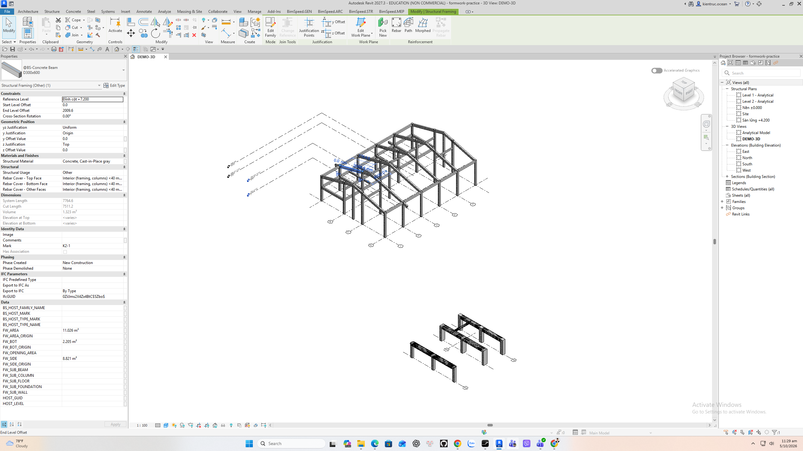
Reading the retained Properties evidence
This is the retained Revit 2027 beam case, not a new runtime run. 1. Host area fields: FW_AREA 11.026 m²; FW_BOT 2.205 m²; FW_SIDE 8.821 m². Compare quantities from the same host/scope. Other category/link combinations remain unverified.
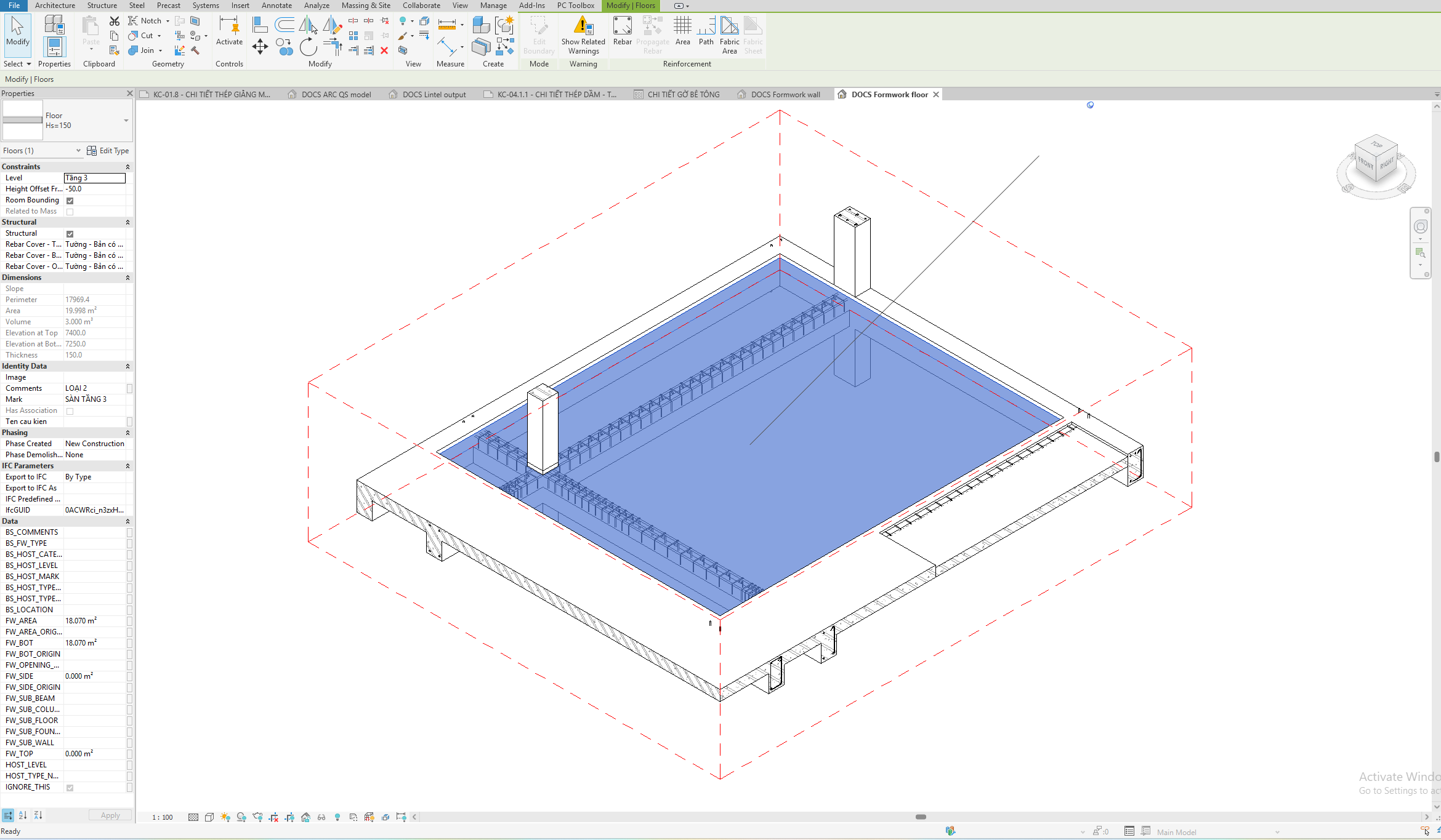
Native Wall/Floor and additional categories in Revit 2024
Area fields were prepared in the copy before running. This example uses the tool's own native-document intersection filter; a calculation without FW_AREA is not counted as a successful write. ① The selected Floor has FW_AREA = FW_BOT 18.070 m², with FW_SIDE 0. ② Its physical Area 19.998 m² and Thickness 150 mm are different quantities. Nine intersection candidates were considered; original formwork area 22.694 m² became 18.070 m². Do not add physical floor Area to FW_AREA.
| Selected native host | Written FW_AREA, m² | Scope |
|---|---|---|
| Wall | 0.445 | Four intersection candidates; separate from the Floor. |
| Floor | 18.070 | Nine candidates; side formwork removed in this case. |
| Column | 3.966 | The filter returned zero candidates for this host. |
| Beam | 10.311 | Side 7.295 + Bottom 3.016; one host, not all project beams. |
| Foundation | 14.879 | One native host; foundation side processing. |
These are host quantities, not project totals. The model warning indicator remains visible: inspect Show Related Warnings before issuing drawings. Set Project Units → Area accuracy to 0.001 m² to prevent 0.5979 m² displaying as “1 m²”. Formatting changes display precision, not geometry or calculated quantity.
In the tab below, ① Add parameters enables ② the name, list and Remove/Add/Create controls. This tab creates optional Text fields. Follow the Area preparation steps; Create Text is not a substitute for an Area FW_AREA. The image shows the disabled initial state.