Edit Rebar
Choose the operation you need: reinforce an opening, crank bars through an offset, copy reinforcement to another host, split a set, extend/cut or delete bars. Diameter Setting manages bar types; check Type Properties separately from the geometry of existing bars.
Verification limits are stated for each tool. Dialog captures establish visible controls; created or edited elements require separate checks in the model, Properties and saved RVT.
Logo, Feedback and YouTube actions are explained in the common dialog footer.
Rebar Opening
Open BimSpeed.STR → Edit Rebar → Rebar Opening. Pick a Floor or Wall host, select its openings/shafts, then Finish or press Enter. The opening edges must form a closed loop. An empty or invalid selection may open Help.
| Control | Units / choices / enabling | Effect and verification |
|---|---|---|
| Trimmer | Enables this group's fields | Bars along opening edges; disable it to test corner bars separately |
| Layer — Trimmer | Both / Top / Bottom for floors; Front / Rear for walls | Inspect the selected host faces in section |
| Bars per layer — Trimmer | Integer, per reinforcement layer | More bars along each edge; distinguish each set's Quantity from the overall total |
| Center to center — Trimmer | mm | Centre spacing within this group; measure centre lines rather than outside faces |
| Bar Type — Trimmer | Project Rebar Bar Type | Sets the edge-bar type/diameter; verify a selected bar's Type Properties |
| Anchorage length — Trimmer | mm | Extends the edge bar at each end; measure both extensions |
| Cover offset 1 / 2 — Trimmer | mm; corresponding opposite edge/face pairs | Adds an offset relative to host cover; it does not replace the host cover setting. Check both edge pairs in section |
| Diagonal | Enables its independent fields | Corner reinforcement, configured separately from Trimmer |
| Layer / Bars per layer / Center to center — Diagonal | Layer; integer per layer; mm | Verify corner-bar layer, quantity and centre spacing |
| Bar Type — Diagonal | Project Rebar Bar Type | Requested corner-bar type; verify the actual type at each corner after creation |
| Anchorage length — Diagonal | mm | Total straight diagonal-bar length, half on each side of its placement centre; different from Trimmer's per-end extension. Measure the entire diagonal |
| Cover offset 1 / 2 — Diagonal | mm, enabled with Diagonal | Moves the corner group relative to its edge/face pair; check with actual host cover |
| Stirrups / Spacing | Enable stirrups, then enter spacing in mm | This window has no separate stirrup Bar Type selector. Verify actual type, host and positions |
| Illustrations / scroll region | Scroll through the examples | Explains placement; it is not committed reinforcement |
| Help / OK / ✕ | Open selection help / accept settings and run / close | Inspect real bars, host and warnings after OK; closing the dialog is not proof of successful creation |
On a separate model copy, create Trimmer bars only, record set count and total Quantity, Undo, then repeat with Diagonal enabled. Change one spacing/count at a time. Inspect the real bars and warnings before saving. Creation around an opening has not yet been verified in this supplement.
Edit Rebar
This command cranks bars through an offset. H (mm) controls the offset; W (mm) controls the transition length. Source defaults are 50 mm and 300 mm. Auto / Down / Up selects direction; Auto processes longitudinal bars before stirrups.
Click Run, select eligible Rebar, Finish, then pick P1 and P2 on elements. Close/Escape closes or cancels selection. Compare centre-line geometry and transition length before/after, including stirrups. Undo must restore geometry. H/W are not diameter or distribution-spacing inputs.
Copy Rebar
Pick the source host containing reinforcement, then one or more target hosts, and Finish. The target-picking loop continues until Escape; each confirmed target batch creates a Copy Rebar transaction.
Record sets and Quantity for source/targets first. Check target Host, diameter, shape, cover and layout afterward. Start with matching host geometry, then test rotated/different hosts on a separate copy. Undo corresponds to a confirmed target batch. Runtime selection and copying remain unverified in this supplement.
Delete Rebar
Enable the host categories to process: Walls, Beams, Columns, Floors, Foundations. Run uses eligible preselected hosts or starts host picking followed by Finish. Close closes the dialog and may persist category choices.
This deletes host reinforcement rather than the concrete host. Compare Rebar/Area/Path counts per host before/after and confirm that the host remains. Undo must restore the actual elements. This differs from Hide/Rebar Visibility. A delete/Undo run remains unverified in this supplement.
Explode Rebar
Select Rebar sets and Finish. A set with Quantity ≤ 1 is retained. Multi-bar sets become individual Rebar at their included bar positions. More sets does not mean more physical bars. The varying branch processes geometry at each position and can replace source element IDs.
Record Number of Bar Positions, omitted positions, Quantity, shape and bar centres. Afterward compare total Quantity and every centre position, host and parameters. Test omitted end bars separately, then Undo to recover the original set. Controller evidence, when available below, does not establish every varying case.
Observed result and position discrepancy
For a D25/M_00 beam set with Quantity 2, the Explode controller produced two Single, Quantity 1 bars, each 5271 mm long. Centre-line readback found both positions shifted inward by 2.5 mm; Undo restored the original coordinates. This result therefore did not meet position-preservation verification. Compare each centre line and host in section/3D before saving; Undo and retain the original set if a position changes unexpectedly. This observation does not establish every shape/layout or the entry-command flow.
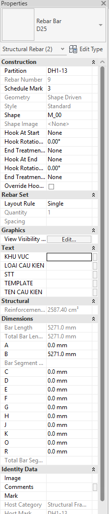
1. Two Rebar elements selected, rather than one Quantity-2 set. 2. Each has Single layout and Quantity 1. 3. Bar Length remains 5271 mm; preserved length alone does not prove preserved centre positions.
Extend Rebar
Cover uses the host-face cover; Offset face enables Length (mm); Explode permits splitting a set when individual bars require separate treatment. Click OK, select bars and Finish, then pick a planar face on their own host. Another host or a curved face does not satisfy this flow.
Measure end points, cover and actual length after each picked face. Offset direction can shorten or extend a bar; verify geometry on a copy. With Explode enabled, compare set count and total Quantity. Escape ends face picking; settings may be saved afterward. Extend/trim and Undo remain unverified here.
Cut at Point
Select a Rebar to configure Lapped bar / Cranked bar / Coupler. Lapped bars use a diameter multiplier or Length (mm). Cranked bars add multiplier/transition length and Auto/Down/Up direction. Couplers require a valid Family and Type. Direct length boxes are enabled only in the corresponding length mode.
| Mode / field | Units, availability and check |
|---|---|
| Lapped — multiplier / Length | Choose diameter multiplier or direct mm. The derived length uses the selected diameter and rounding; inspect the displayed length before Cut |
| Cranked — A and B | Separate distance groups, each with its own multiplier or direct length in mm. Do not reuse one group's value for the other. Auto / Down / Up chooses crank direction; inspect both distances and direction in section |
| Coupler — Family / Type | Select compatible loaded coupler content; verify a created coupler element and its type afterward |
| Staggered — multiplier / Length | The checkbox enables stagger controls. Choose diameter factor or direct mm; inspect alternate joint positions |
| Diameter | Read-only reference in mm; it is not a diameter-edit control |
| Rounding | Length multiple in mm. After changing it, re-enter the multiplier and check the displayed derived length; changing the multiple alone may leave the previous length displayed |
| Cut / Close | Cut continues to point picking; Close exits this window without proving an edit |
Staggered enables stagger distance, entered by diameter multiplier or mm. Rounding (mm) is the length-rounding multiple for diameter-derived lengths; the source lap branch rounds upward. For example, 33×16 = 528 mm rounds to 530 mm at a 10 mm multiple. Use a positive rounding multiple when rounding is required, and measure the actual result. This arithmetic example is not a splice-design recommendation. Cut starts the selected operation and point picking; Close cancels. Pick a suitable point on the bar rather than its host.
Use a separate copy for each mode. Compare set count, Quantity, lengths and joint locations. A coupler case needs a real coupler element. Undo must restore both bars and couplers. No cut case has yet been verified in this supplement.
Diameter Setting
Open BimSpeed.GEN → Link → Diameter Setting. This shared command is documented once. The table contains Name, Model Bar Diameter, Bar Diameter, Standard Bend Diameter, Standard Hook Bend Diameter, Stirrup/Tie Bend Diameter, Maximum Bend Radius. Diameter/radius values use the table's mm convention; distinguish each bend field.
| Column | Units and effect to verify |
|---|---|
| Name | Type name; nonempty and unique without case distinctions. Check whether the name updates an existing type or creates another type |
| Model Bar Diameter | mm. Do not rely on this column to preserve a separate model diameter: the reviewed apply flow sets Revit model and nominal diameters from Bar Diameter. Verify both native Type Properties values after OK |
| Bar Diameter | mm, positive; used to create/update the bar type. Updating a type can affect every instance using it, not just selected bars |
| Standard Bend Diameter | mm; standard bar bends, separate from hook and stirrup bends. Check the native type and a representative bend |
| Standard Hook Bend Diameter | mm; standard-hook bends. Inspect the actual hook and its length settings |
| Stirrup/Tie Bend Diameter | mm; stirrup/tie bends. Verify a stirrup rather than using a longitudinal-bar screenshot as evidence |
| Maximum Bend Radius | mm, a radius rather than a diameter. Read back the native type; some versions/values may reject assignment without stopping every other update |
The reviewed apply flow can adjust bend diameters smaller than Bar Diameter and reset some oversized/manual hook-length settings while updating types. Therefore compare saved Type Properties, actual hooks, cover and bar centres with the inputs; a closed dialog does not prove every entered value was kept. These behaviours have not been verified by an OK/write case here.
Get from Revit reads existing Bar Types. OK validates nonempty unique names and positive diameters, saves the catalog and Project Information mode, and creates/updates common Bar Types. Close closes the dialog. Verify Type Properties and a representative bar afterward; editing a catalog alone does not prove an existing bar changed diameter. Use a model copy.