Column Rebar — Classic — Practical guide
Recorded in Revit 2027.3 with the English interface. Number 1 identifies the controls or result discussed immediately above the image. Click an image to open its full resolution.
Verification scope
Basic cage creation is verified. The instructional family solid is 3048 mm high while its system length is 4000 mm: reinforcement extends above the solid. Do not treat this fixture as a coordinated final detail. Additional closed ties, crossties, separated bars and foundation settings are preview demonstrations. The separate frame generation failed inside Revit; no advanced successful result is claimed. Re-running can duplicate reinforcement.
Settings reference · Practice RVT · All five guides
Video — English (6:38)
English transcript · English subtitles SRT · Chapter titles
Google Gemini Charon narration, directed in neutral American English. Chapter cuts, brief zooms and highlights follow the measured speech. Enable English subtitles in the video player.
1. Choose the classic command (0:00)
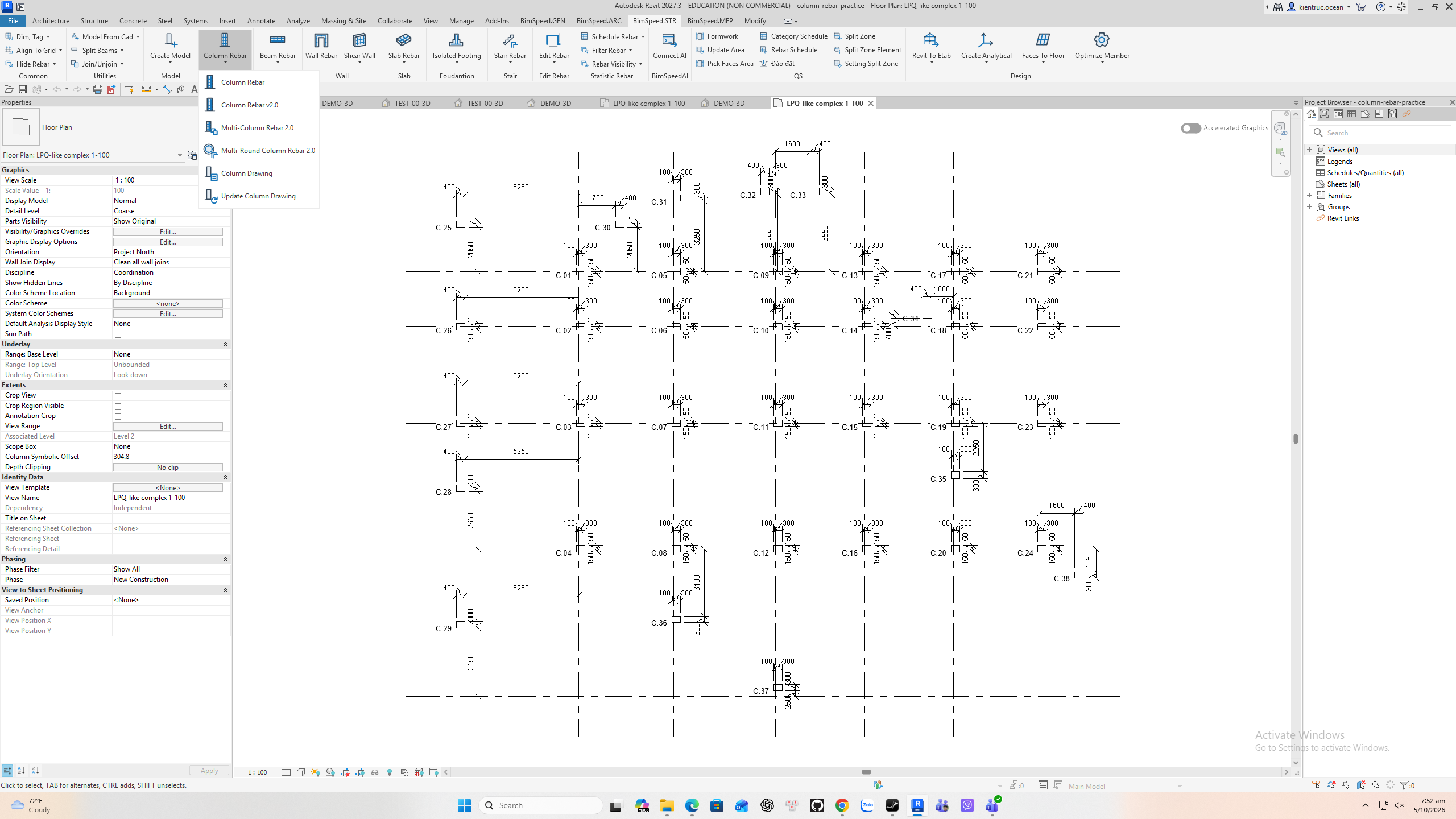
Open BimSpeed dot S T R, Column Rebar, and the first Column Rebar item. This guide uses the classic command, not Column Rebar version two. Select one vertical column per base level, then Finish. For a vertical stack, select the corresponding columns across levels. Multiple columns on the same base level are rejected by this classic workflow.
2. Read the host and section settings (0:24)
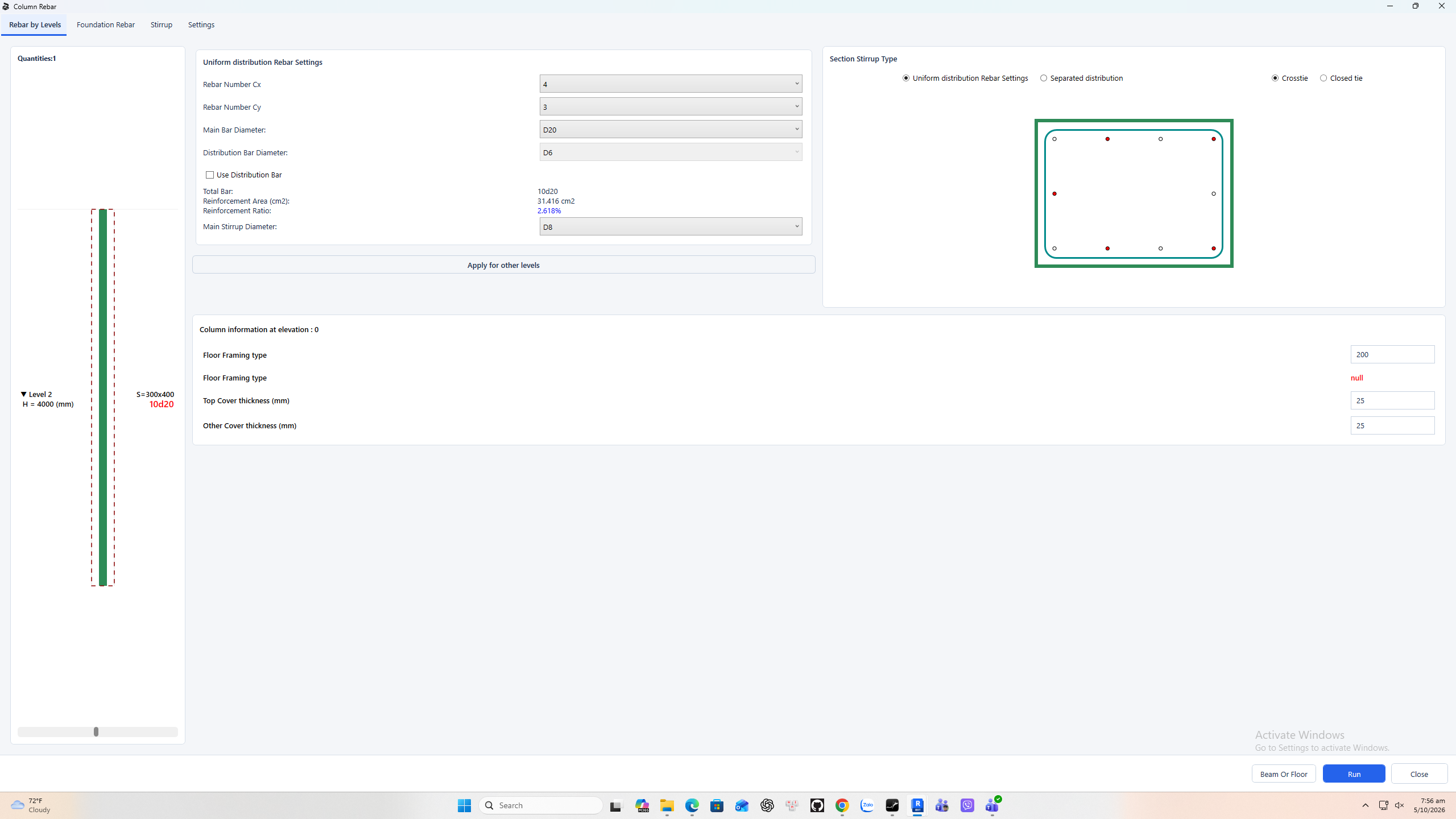
In Rebar by Levels, select the level and check the section size, height, covers, and beam or floor association. This example is a three hundred by four hundred millimeter column. Set C x to four, C y to three, main diameter D twenty, and main stirrup diameter D eight. The preview reports ten main bars, because corner bars belong to both face counts. These are example software inputs, not a design recommendation.
3. Distribution and separated layouts (0:53)
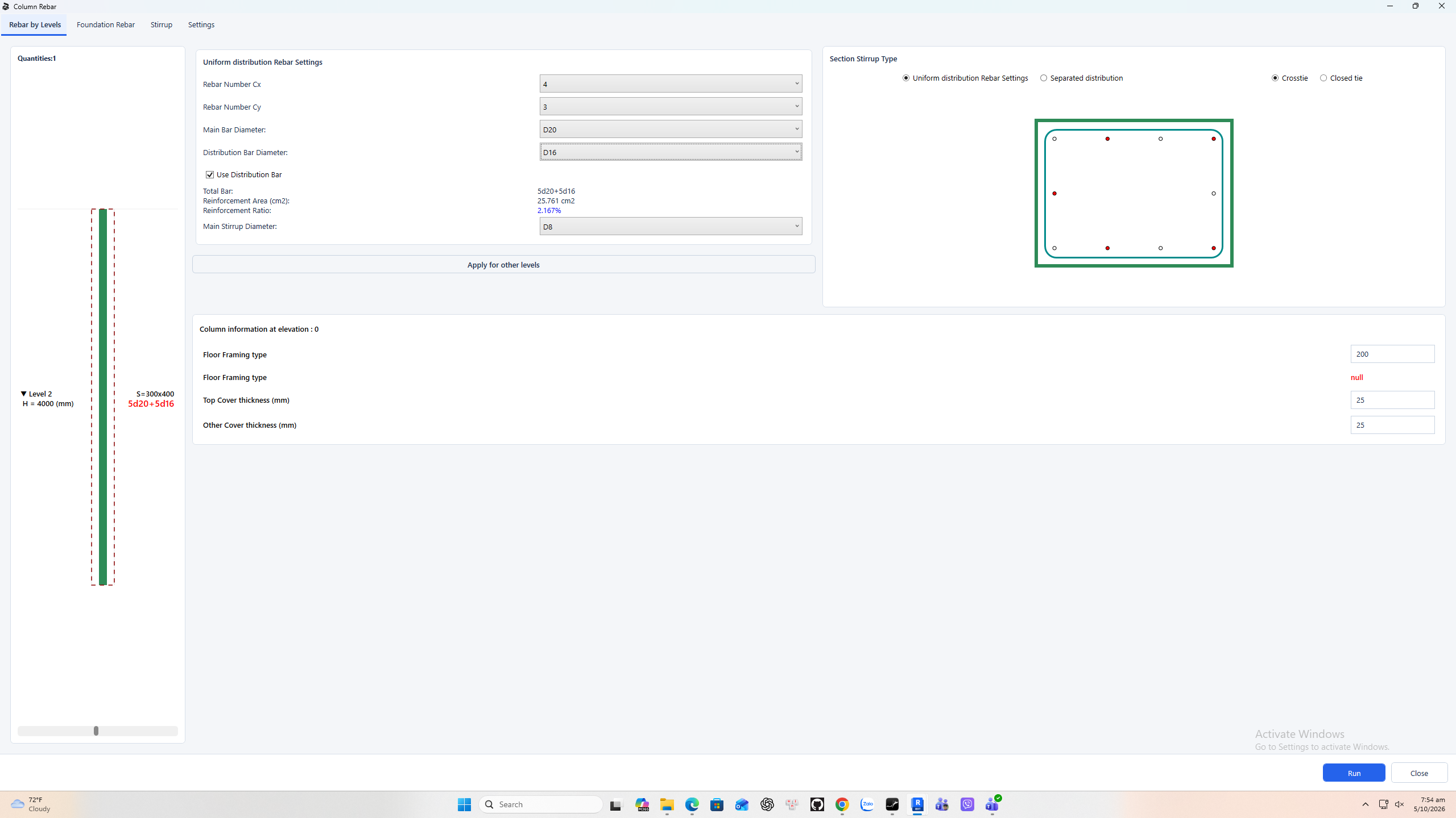
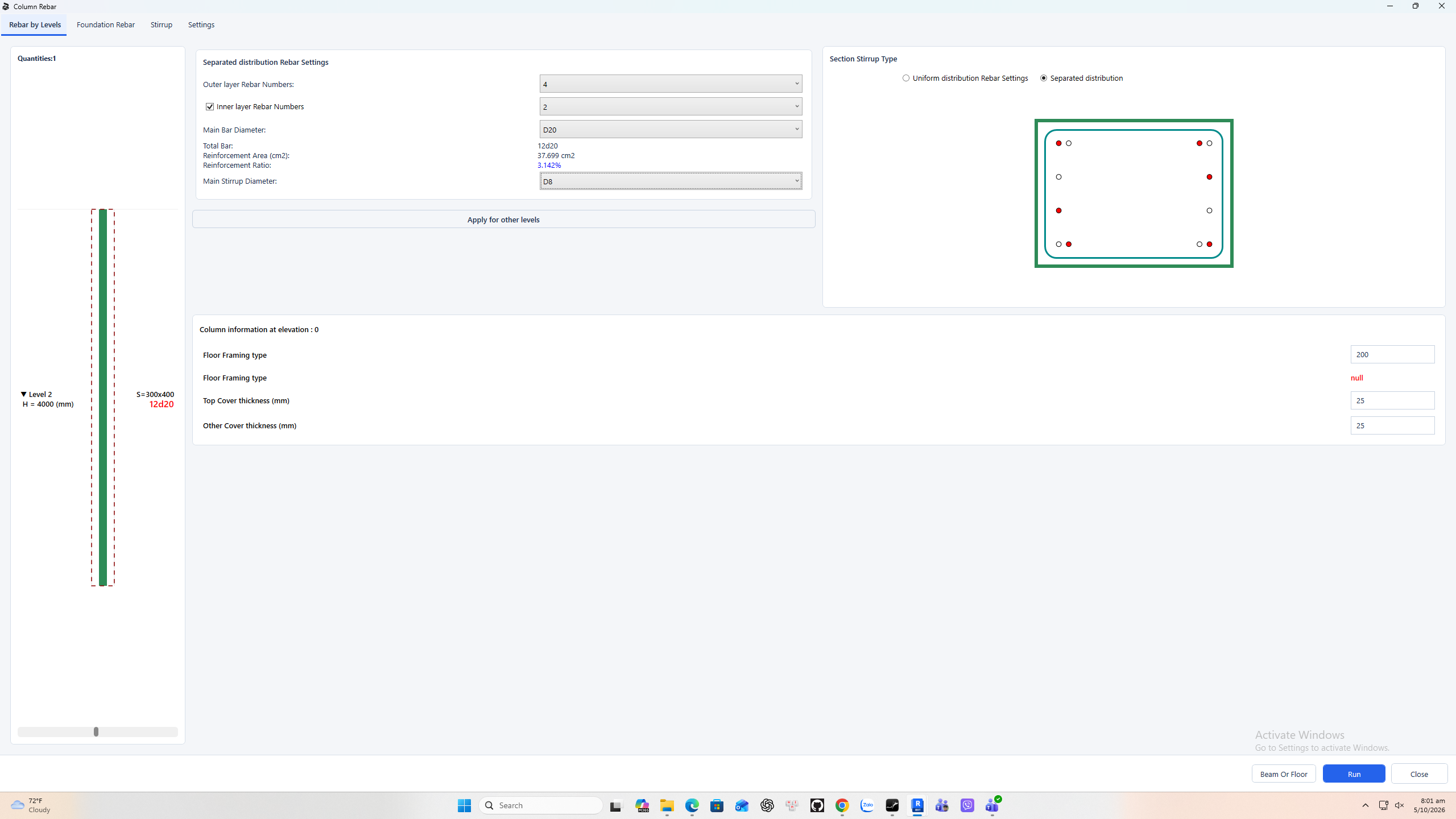
Use Distribution Bar introduces the separate distribution diameter. Inspect which positions change in the section instead of treating it as a replacement for every main bar. For separated distribution, switch the section layout radio. Set Outer layer Rebar Numbers, enable the inner layer if needed, and set its count. The layout has its own diameter choices: check them after switching.
4. Separated layout controls (1:18)
This screen shows the separated distribution controls after changing the outer count and enabling the inner layer. Compare the section preview and total before running. Apply for other levels opens copying only when more than one level is available. In a single-column selection there is no second level to receive the settings. After copying, inspect each target level and its host dimensions.
5. Draw an inner closed tie (1:40)
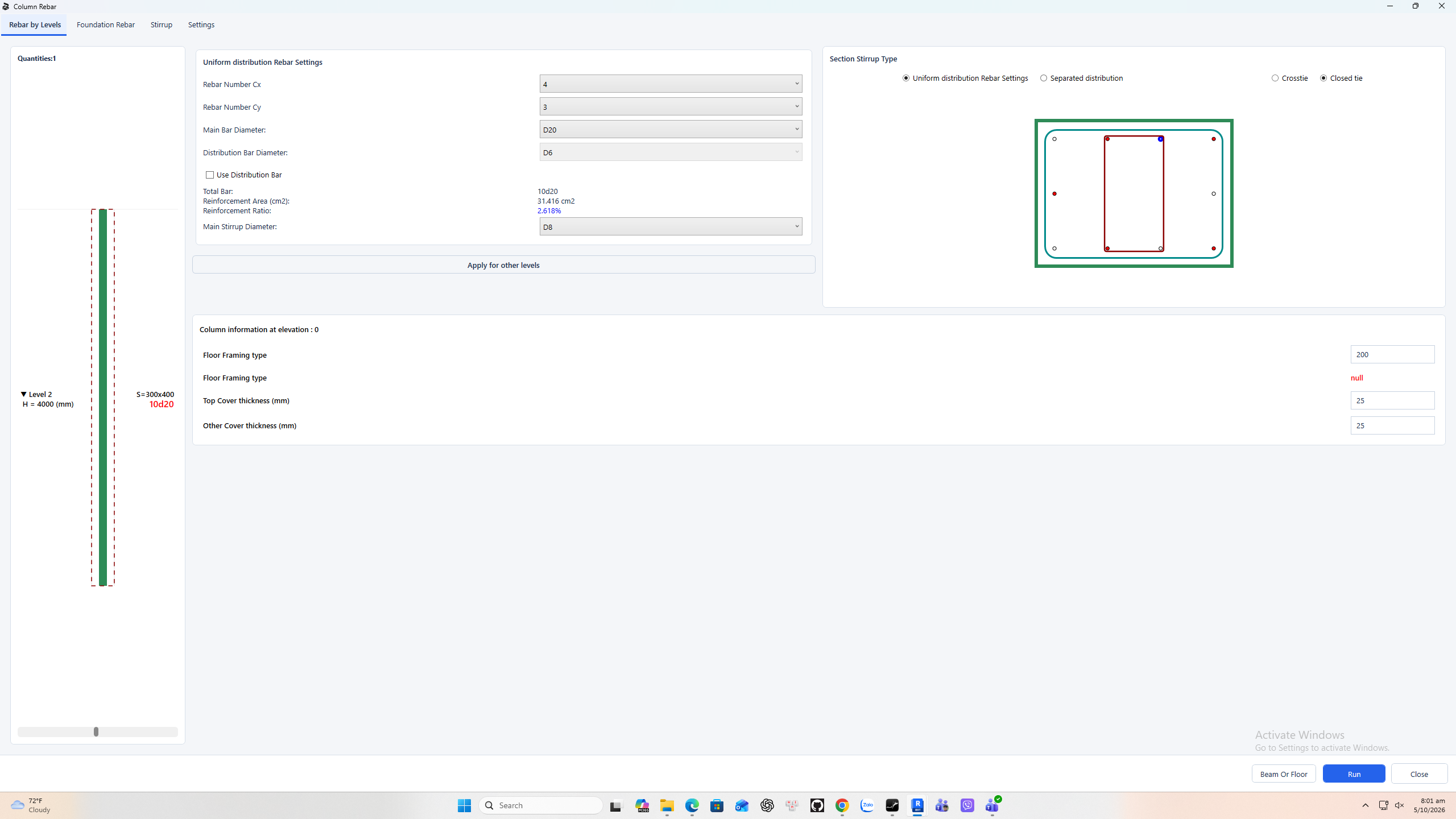
For a closed inner tie, select Closed tie. Move to the first longitudinal bar on one side of the section and click. Move to a different bar on that same side and click again. The rectangle spans between those positions and the opposite side. Selecting the identical bar twice raises an error. Points on different sides can also be rejected. This capture verifies the preview interaction; it is not a separate successful generation test.
6. Draw a crosstie (2:08)
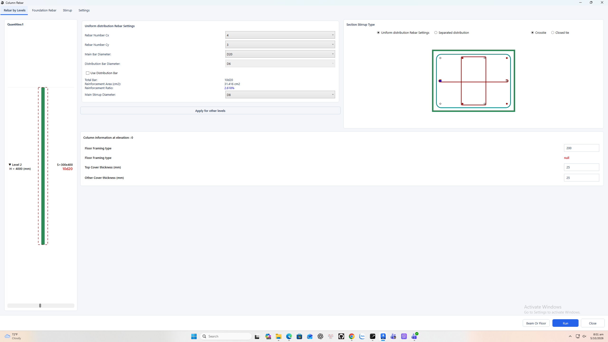
Select Crosstie, then click the required longitudinal bar position in the section. The preview draws the tie across the section. Pause over the bar so it highlights before clicking. In the Stirrup tab, set the additional tie diameter, hook type, and whether its spacing follows the main stirrup. If it does not follow, enter its own spacing.
7. Main stirrup zones (2:31)
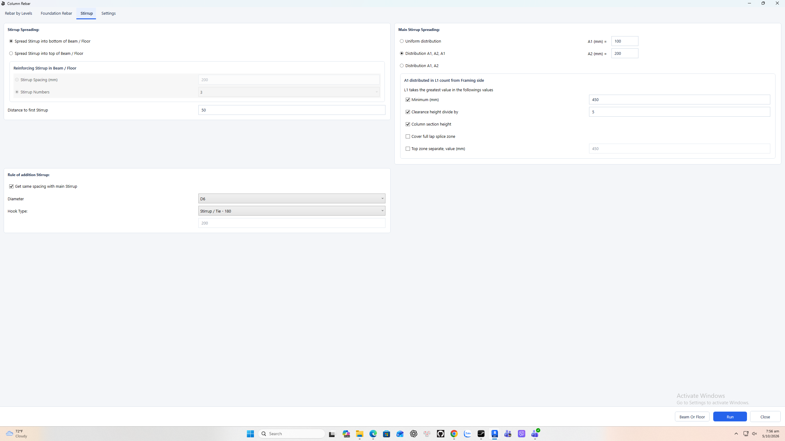
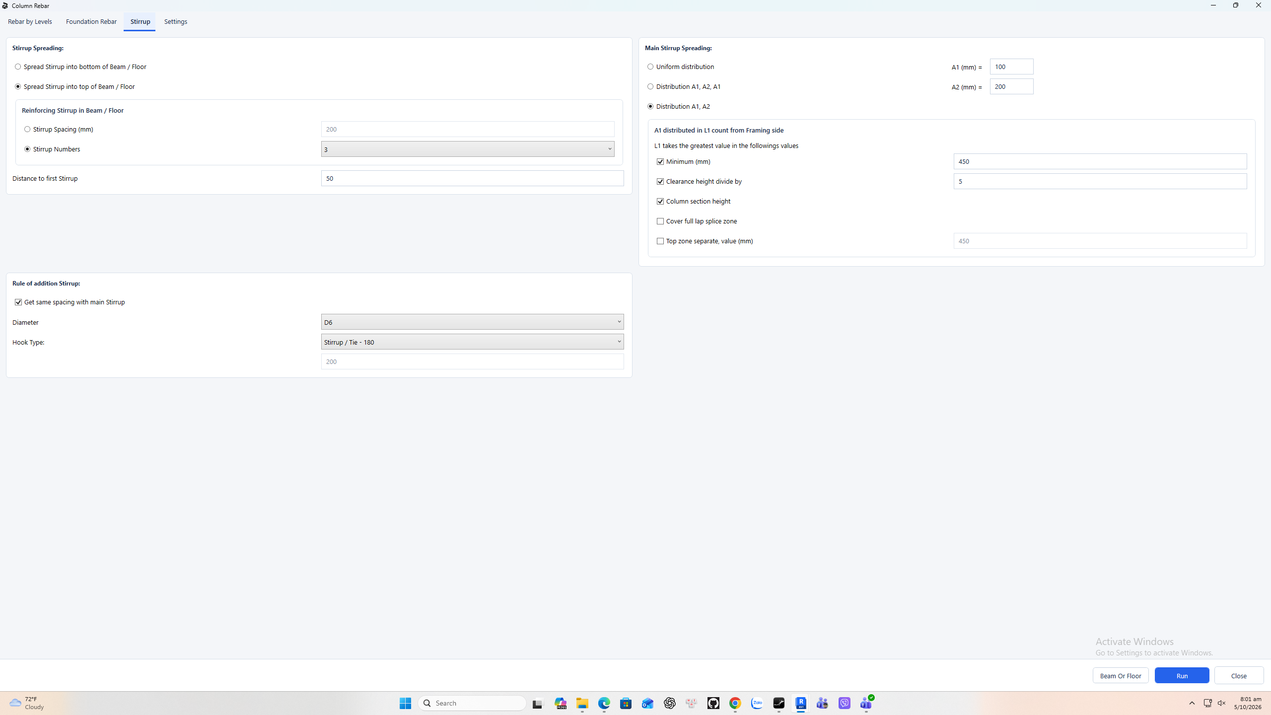
The Stirrup tab offers Uniform distribution, A one A two A one, or A one A two. Here A one is one hundred and A two is two hundred millimeters. Distance to first Stirrup is fifty. For zoned layouts, L one uses the greatest enabled criterion: minimum four hundred fifty, clear height divided by five, and the column section height. Cover full lap splice zone and Top zone separate change the zone extent. Check the resulting positions, not just the spacing fields.
8. Uniform and beam-depth options (3:04)
Uniform uses one spacing throughout its relevant length. A one A two uses two zones; A one A two A one provides end zones at both ends. Spread Stirrup into top of Beam or Floor enables reinforcement in the beam or floor depth by spacing or number. Spread into bottom stops at its underside. The classic Run validation still requires at least one of the minimum, division, or section-height criteria to be enabled.
9. Foundation starter settings (3:32)
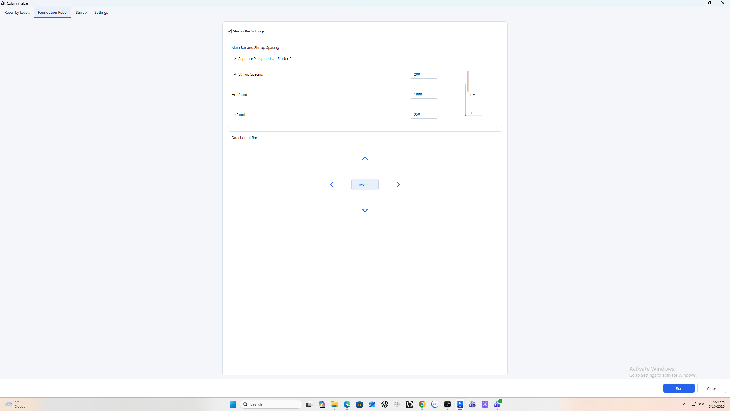
For a foundation starter case, enable Starter Bar Settings. Separate two segments at Starter Bar separates the starter and column bar arrangement. Enable Stirrup Spacing to add foundation ties; this example shows two hundred millimeters. H m is one thousand and L b is three hundred fifty. The arrows and Reverse change bar direction. Match these values to the actual foundation geometry. In this session the advanced frame generation failed, so these foundation controls are documented as settings, not verified output.
10. Hooks, continuity, and lap positions (4:05)
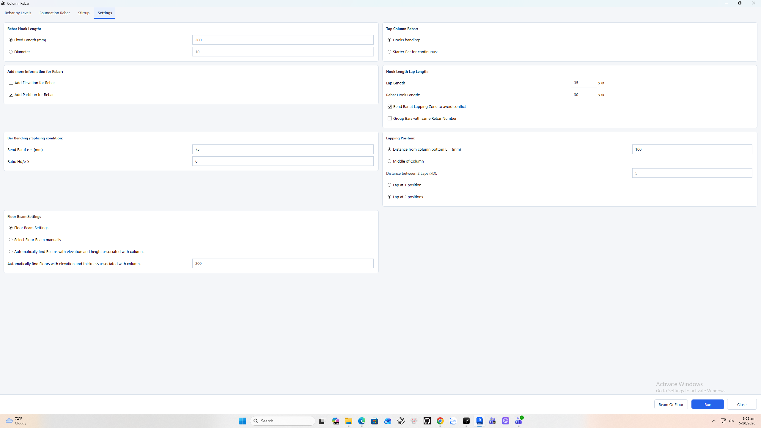
In Settings, choose top Hooks bending or Starter Bar for continuous columns. Rebar Hook Length can use a fixed length or a diameter multiplier. The lap group separately specifies Lap Length and Rebar Hook Length as diameter multiples. This screen shows thirty five and thirty. Choose the distance from the column bottom or Middle of Column, then one or two lap positions. The distance between two laps is a diameter multiplier. Bend Bar at Lapping Zone changes offsets; grouping affects bars with the same number.
11. Host association and information (4:40)
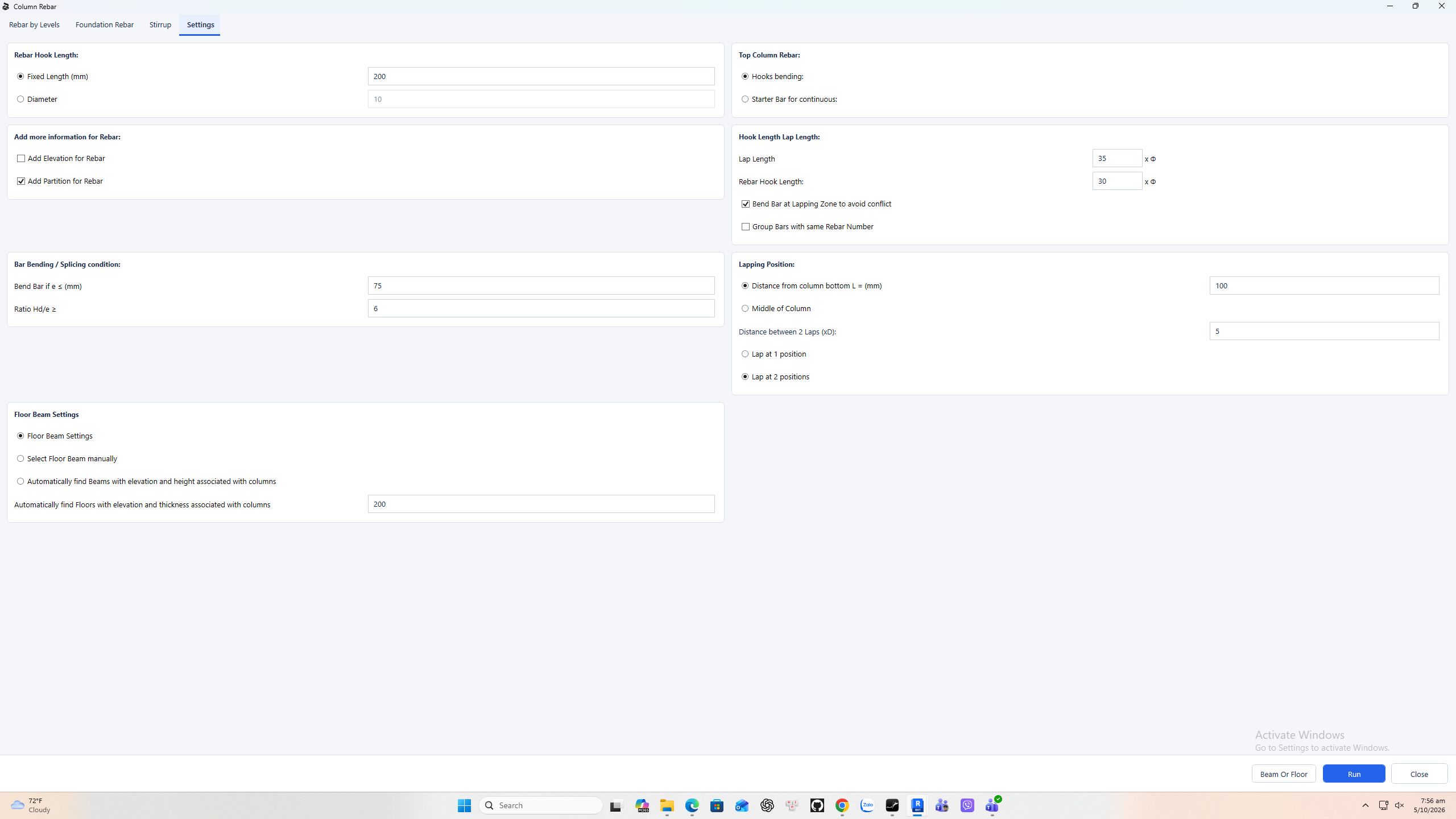
For changing sections, the bend condition uses offset e and the ratio H d over e. Add Elevation and Add Partition write information to bars. The Floor Beam Settings group controls a default depth, manual selection, or automatic beam detection. When manual selection is active, use Beam Or Floor and select the intended supports. A red null association is a prompt to inspect the host context. Do not treat an assumed two hundred millimeter depth as an automatically detected beam.
12. Run and inspect actual rebar (5:13)
Run saves settings and creates reinforcement. In the first practice model, the selected D eight stirrup set uses shape M T one, one hundred millimeter maximum spacing, and a quantity of seven in the displayed zone. This quantity describes the selected set, not all ties in the column. To inspect the cage, select the host, use Selection Box, and enable Unobscured in the active three dimensional view.
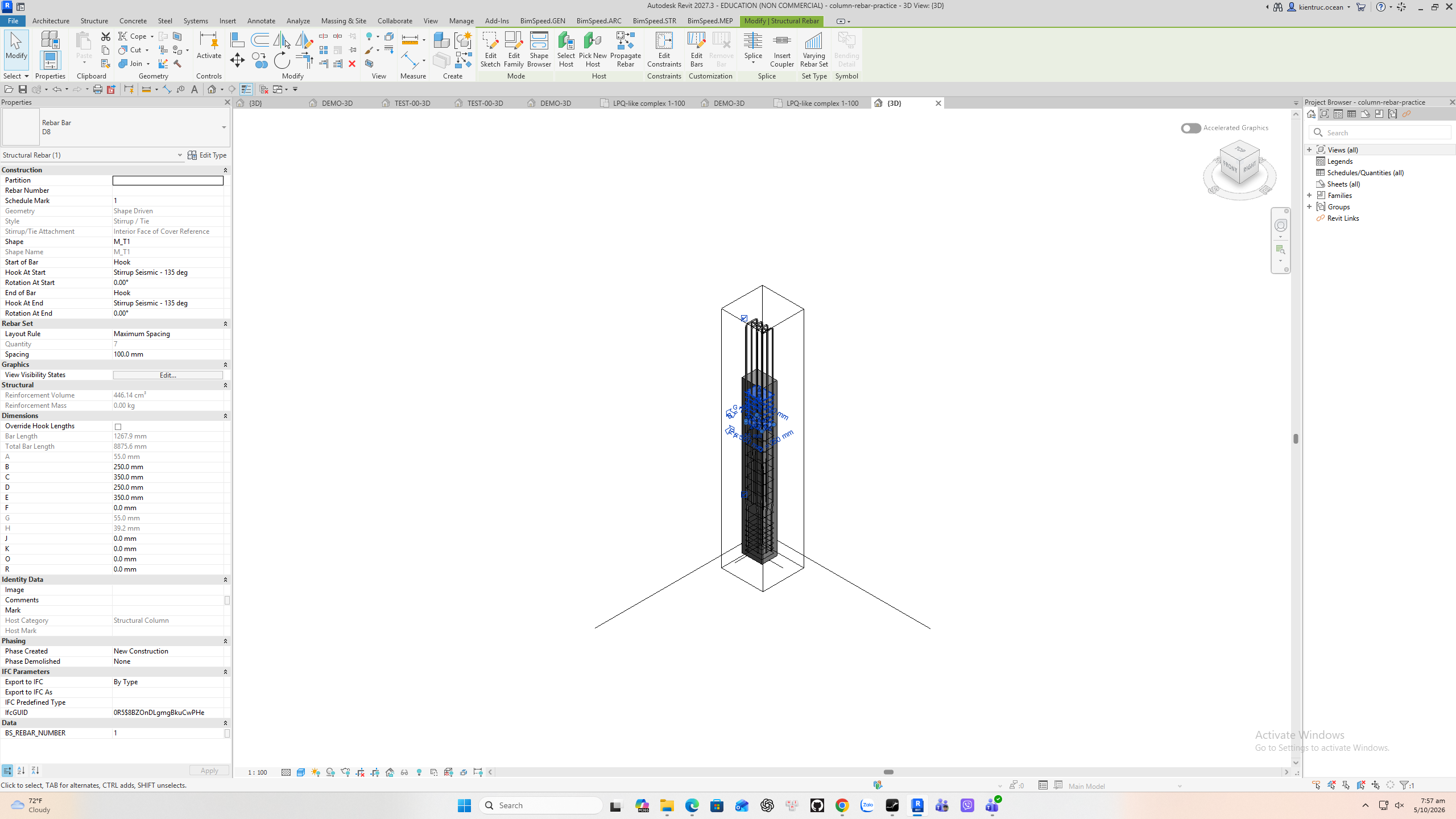
13. Check the model limitation (5:39)
The created cage is visible here. However, this fixture has a four thousand millimeter system length while its family solid is shorter. The bars extend above that solid. This is a model limitation to resolve before using it as a construction example. The supplied file is retained for reproducing settings and inspecting the created bars, not as a validated reinforcement design.
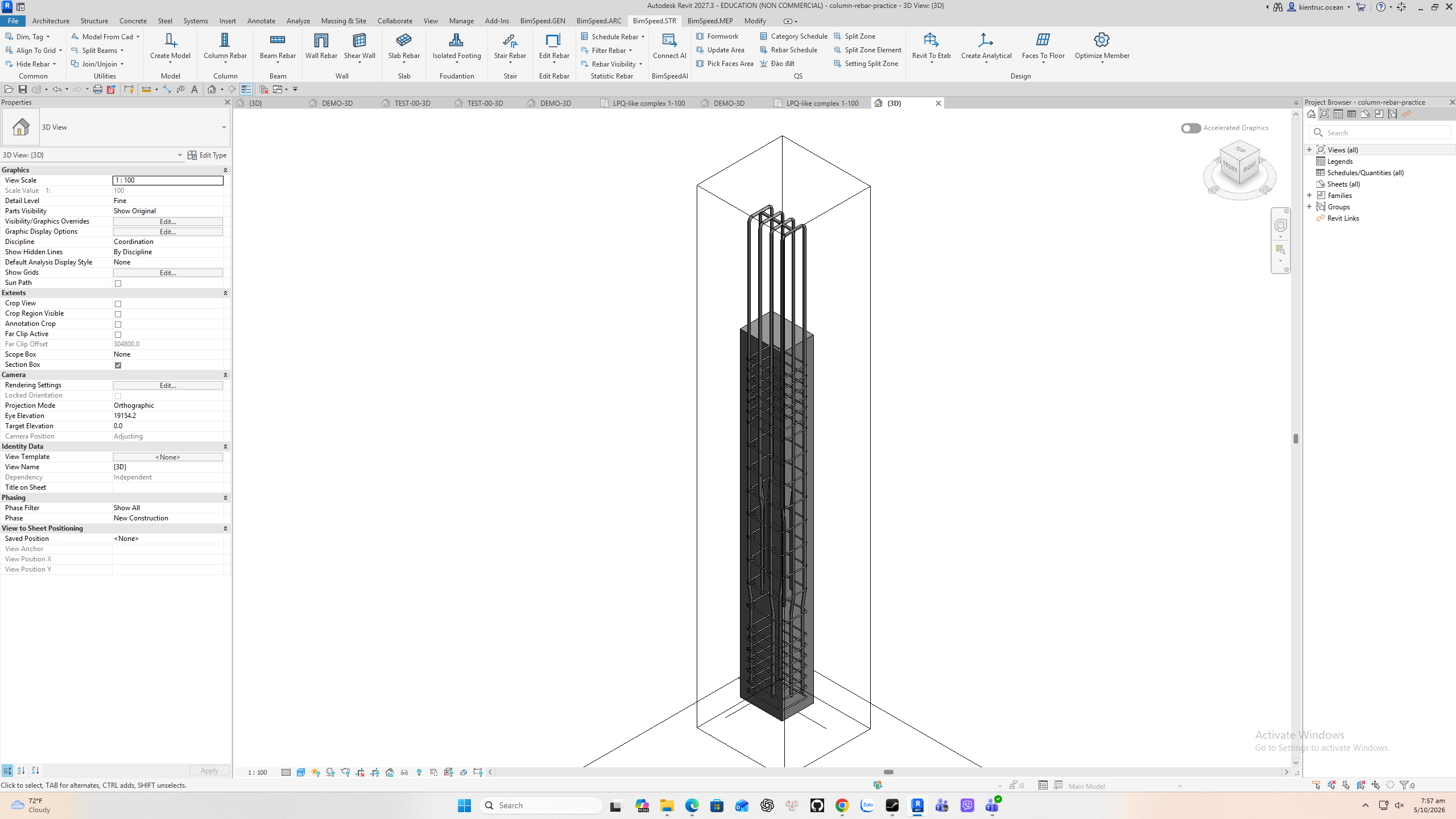
14. Advanced run failure and safe repetition (6:05)
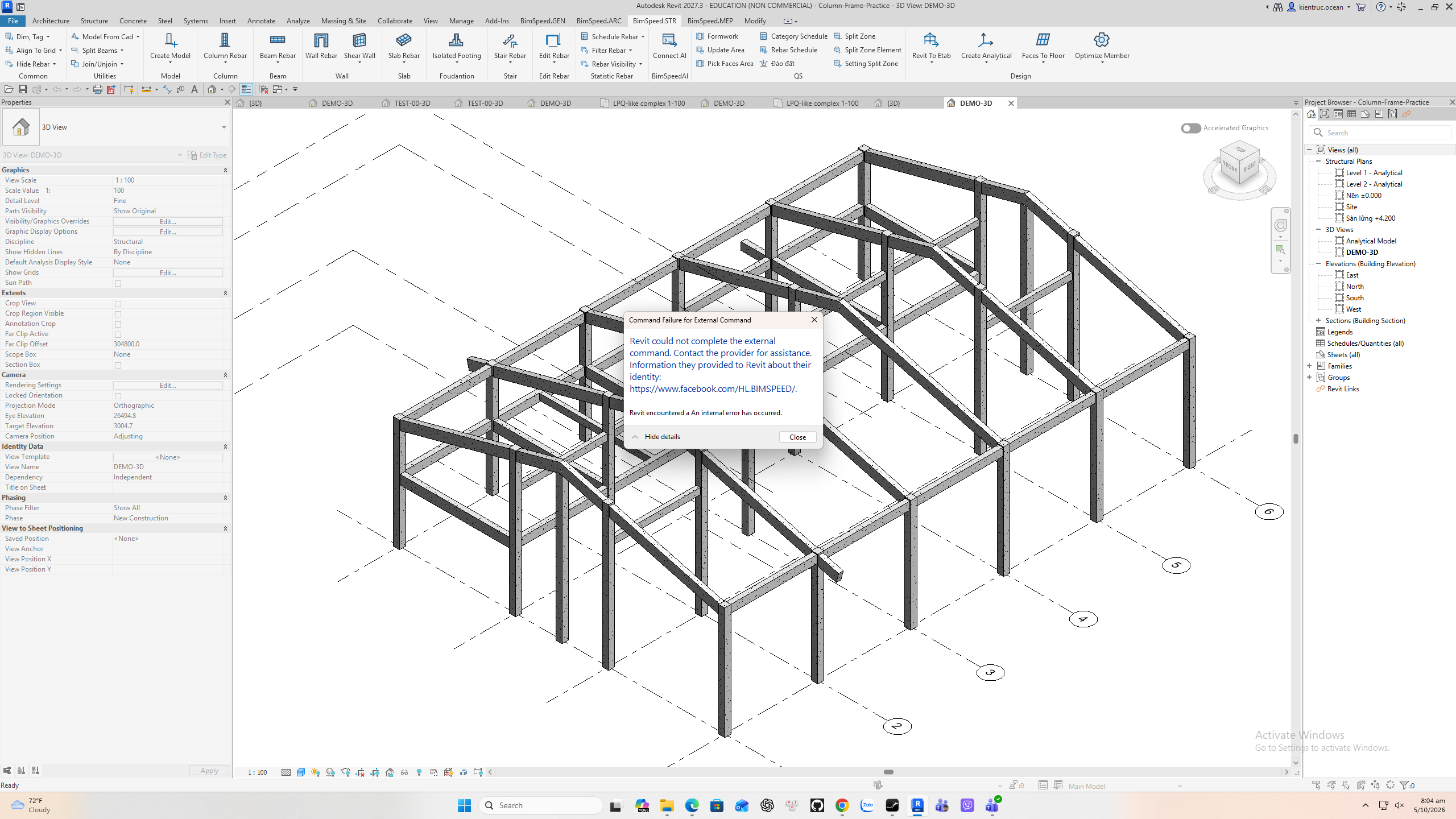
A separate frame model was tested with additional ties and foundation starters. Revit reported an internal error, and its journal identifies a problem evaluating shape M T one. Loading the available BIMSpeed content did not resolve this run. Do not present that preview as generated reinforcement. The classic command creates bars, so do not repeatedly run it over a completed cage assuming automatic replacement. Work on a copy and use a deliberate Undo or removal workflow when repeating.
Practice and safe repetition
Basic cage creation is verified. The instructional family solid is 3048 mm high while its system length is 4000 mm: reinforcement extends above the solid. Do not treat this fixture as a coordinated final detail. Additional closed ties, crossties, separated bars and foundation settings are preview demonstrations. The separate frame generation failed inside Revit; no advanced successful result is claimed. Re-running can duplicate reinforcement.
Download the Revit 2027 practice package, extract the RVT and read README.txt. Save a separate copy before repeating. Use Ctrl+S to save the RVT; saving a tool template alone does not save model changes.
Additional advanced classic evidence
The classic reinforcement processor ran on an educational 300 × 500 × 3500 mm column with foundation starter bars enabled, Hm=550 mm, Lb=300 mm, split segments enabled and foundation ties disabled. It committed and saved 9 sets with a total Quantity of 45: 12 D20 bars and 33 D8 ties. The D20 total includes the roles generated in this case, rather than 12 bars at one section.
This representative case supplements the previews above; it does not verify every advanced classic combination. The illustrated Revit 2024 version does not expose a Side Bars group. Use that part of the reference only when your actual UI includes it; these captures do not illustrate side-bar creation through that group.
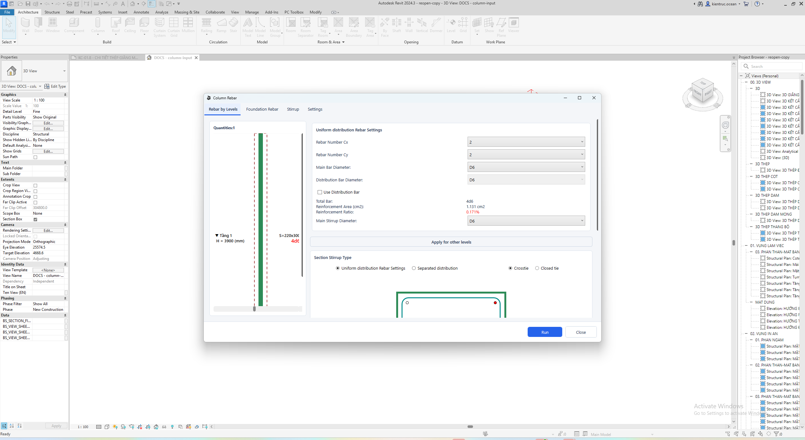
Classic UI on a 220 × 300 × 3900 mm project column: 1: Cx/Cy and bar types; 2: calculated summary; 3: Apply for other levels. The displayed D6 configuration is neither a design recommendation nor the advanced cage counted above.