Column Rebar v2.0 — Main Cases
English Revit 2027.3 demonstration. Verification: Installed v2.0 settings captured; no clean v2.0 generation result is claimed.
Video
Narration: Google Gemini Charon, professional English. The video retains the full Revit screen, briefly zooms on named controls, and includes timed English subtitles. Transcript · SRT.
1. Select the installed v2.0 command
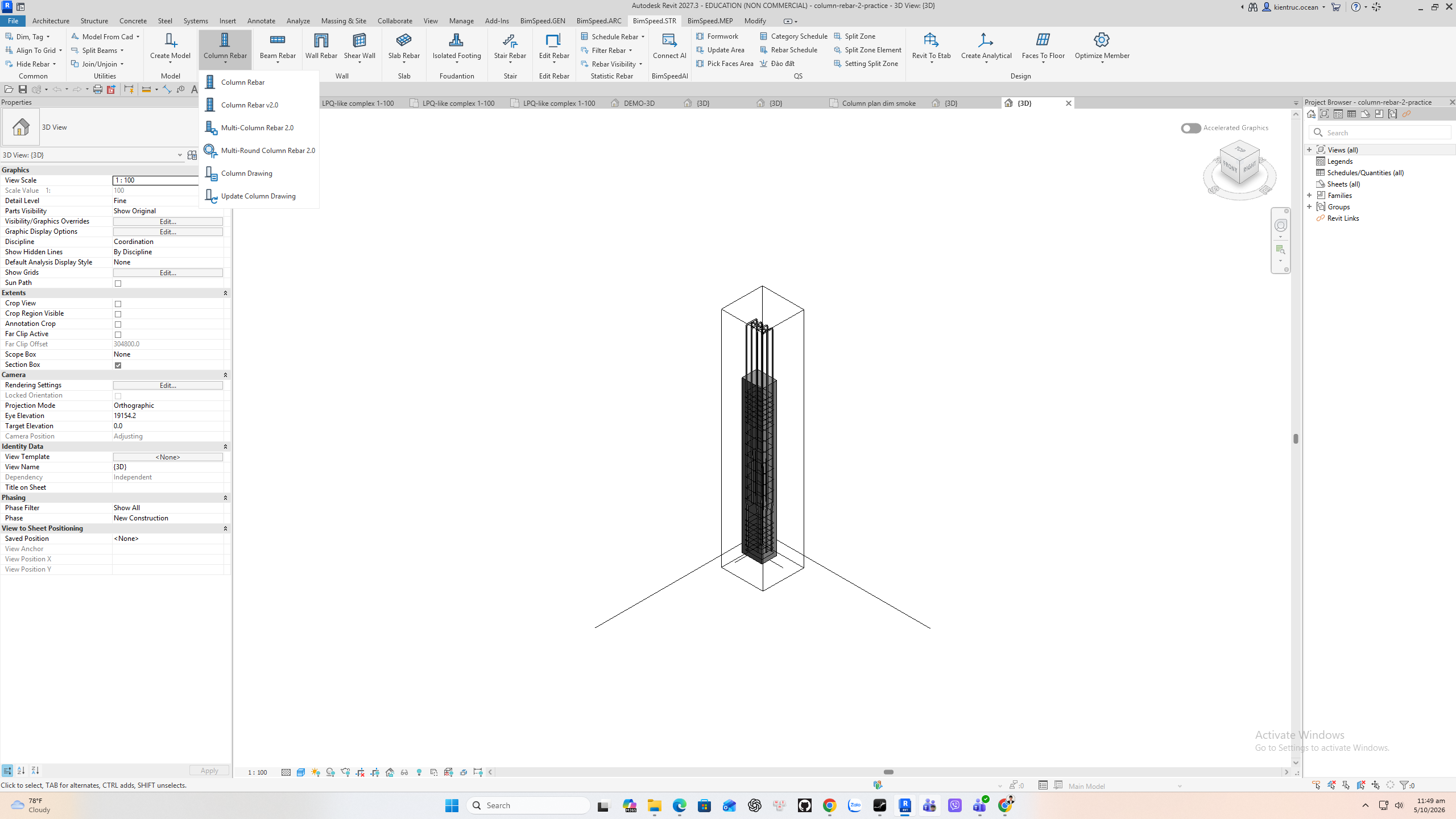
On BimSpeed dot S T R, expand Column Rebar and choose Column Rebar v2.0. The backend rank names ColumnRebarCmd, which is distinct from the classic column rebar tool covered earlier. Work on a copy before creating bars, because an existing cage may be duplicated.
2. Set geometry and longitudinal bars
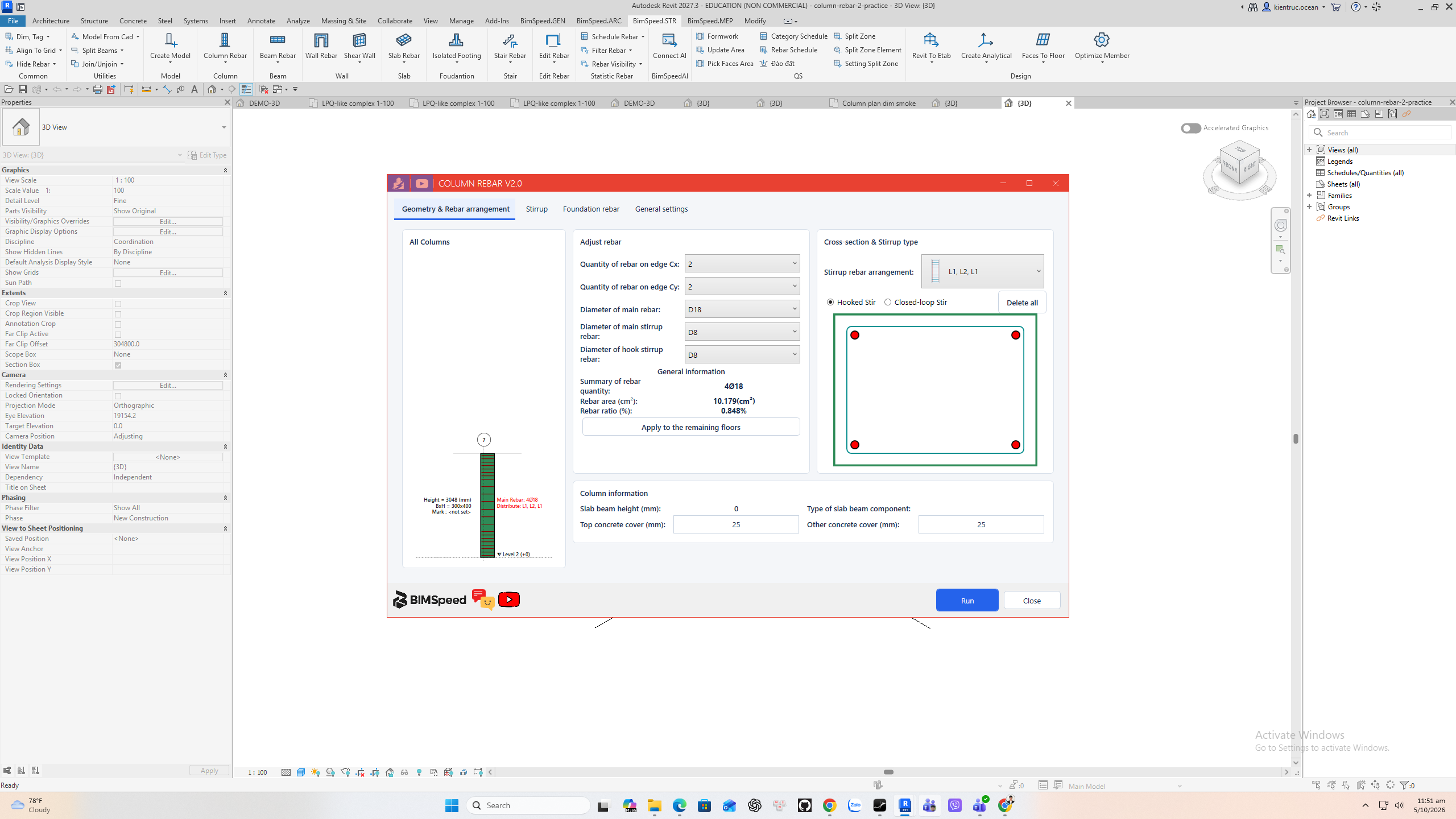
Geometry and Rebar sets cover, main bar diameter, edge counts C x and C y, stirrup diameter, hook bar, and section arrangement. Check the preview and the actual concrete section before applying. The captured example shows D eighteen main bars and D eight stirrups.
3. Set stirrup zones and distribution
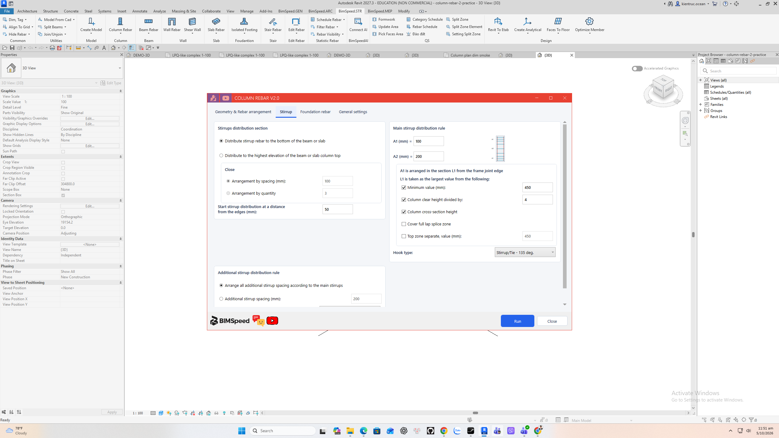
Choose uniform or zoned spacing such as A one A two A one. Enter first stirrup distance, close-zone spacing or quantity, and L one criteria. Review lap and top zones and whether stirrups extend into the beam or slab above. Additional ties have their own diameter, hooks and spacing behavior.
4. Foundation starter bars
The Foundation tab enables waiting or starter bars, split direction, tie spacing, H m and L b. Check the foundation host and the arrow orientation; Reverse changes direction. In this recorded model the tab is a setting demonstration only; no starter bar creation is verified.
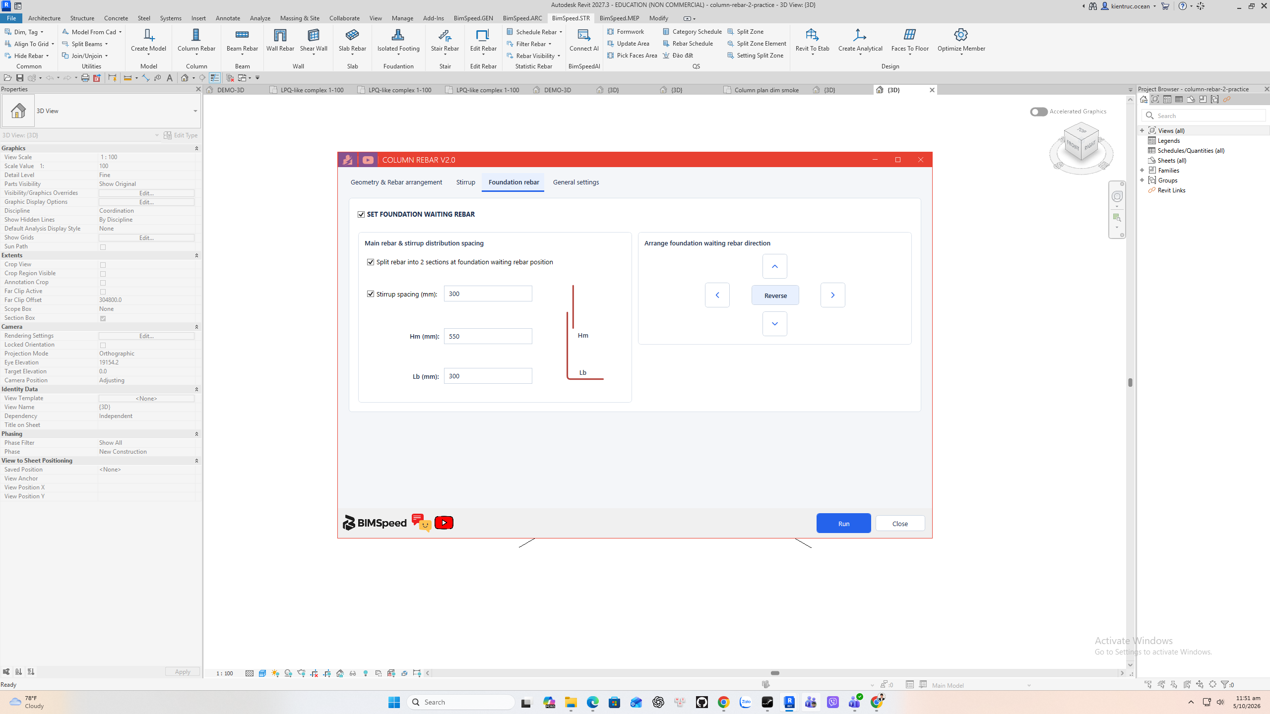
5. General anchorage and run boundary
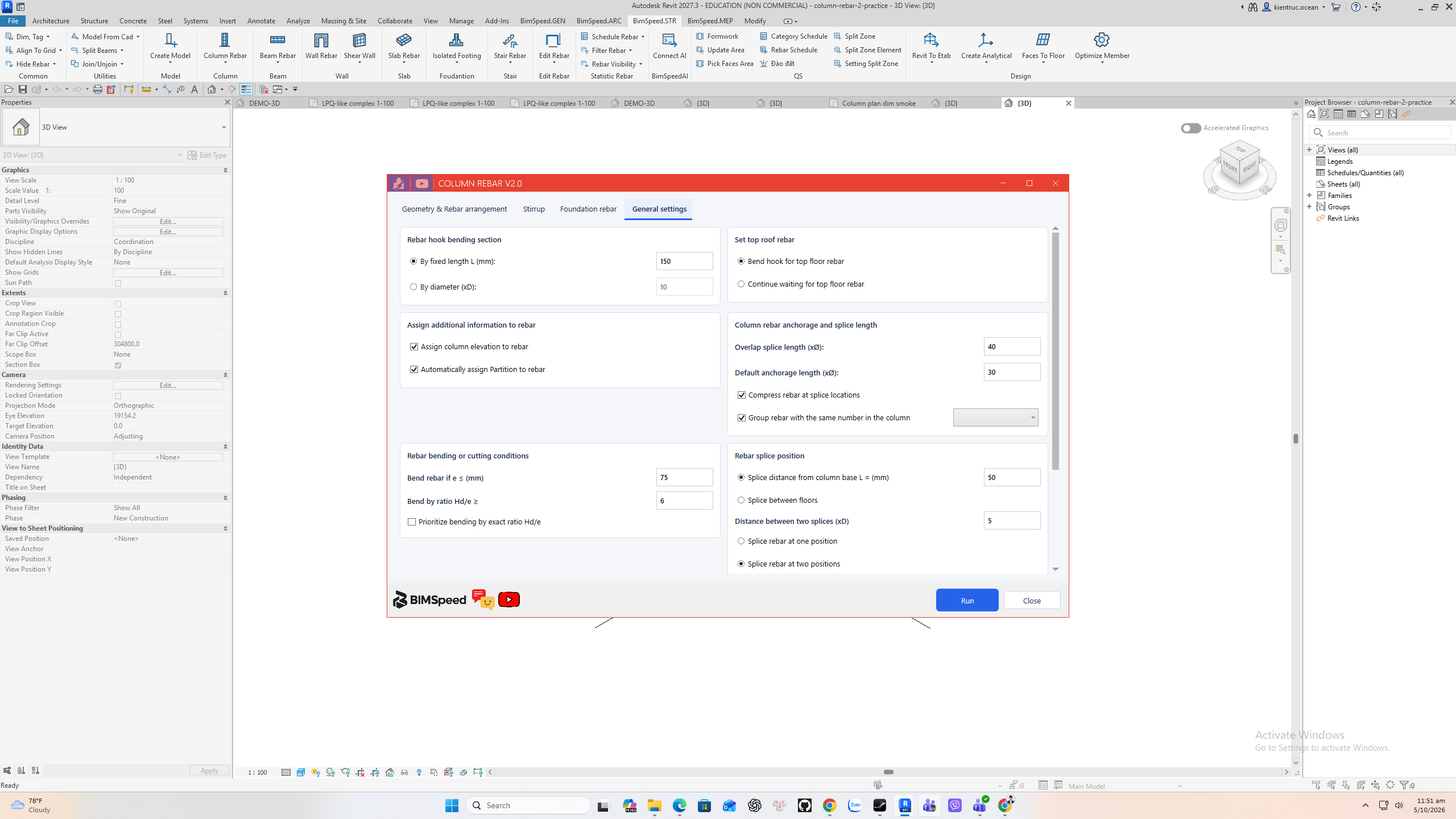
General includes hook choices, lap and anchorage lengths, partition and elevation data, splice position and beam or floor association. The earlier copied model already contains a classic cage, so these v2 settings were not executed over it. A clean-model output check remains required before using it as a completed v2 reinforcement example.
Compare configurations on one project column
The native 220 × 300 mm column is 3600 mm high and initially had no bars. Keep the host fixed while changing bars per face, actual main-bar diameter and uniform tie spacing. This is an upper-story example with foundation starter bars disabled; do not reuse that scope for a foundation-level column.
| Configuration | Cx / Cy | Actual main diameter | Maximum tie spacing | Main bars | Ties |
|---|---|---|---|---|---|
| Initial | 3 / 3 | 16 mm | 200 mm | 8 | 17 |
| Denser | 4 / 3 | 20 mm | 150 mm | 10 | 22 |
| Reduced again | 3 / 3 | 16 mm | 200 mm | 8 | 17 |
Each configuration created and saved seven sets. Set count stays constant while physical bar count changes: sum Quantity by role instead of treating seven sets as seven bars. The project's 16 mm type is named HBIMSPEED; the 20 mm configuration uses 20-A-II. Read Type Properties rather than inferring diameter from a name.
The new elements on this column had no outside-host warning in the saved example. Other pre-existing project elements still have warnings; filter by host/elements to keep the scopes separate. After Save, reopen the correct result and compare a tie set and a main-bar set against Quantity, diameter and spacing.
Read set Properties correctly
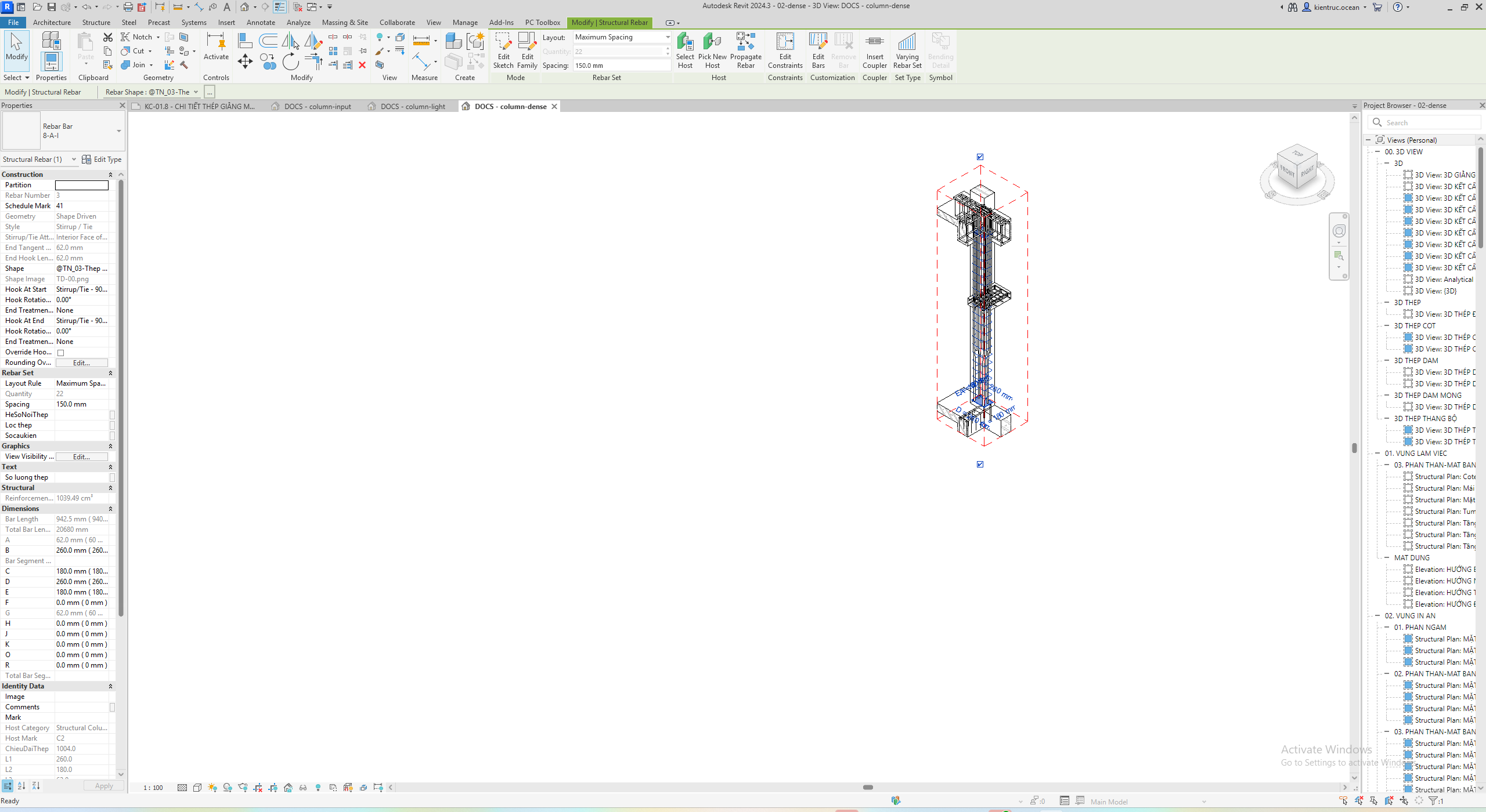
The capture selects a tie set with Quantity=22 and Maximum Spacing=150 mm. This is its tie count, not twenty-two main bars. Under Maximum Spacing, spacing is a layout limit; measure distribution positions when actual interval is needed. This is generated model geometry, separate from a dialog preview.
Review foundation starters separately
An earlier educational 300 × 500 × 3500 mm example contained fourteen sets and fifty-eight bars: twenty D20 bars and thirty-eight D8 ties. One three-tie D8 set was completely outside its host. The D20 total includes main/starter roles, rather than twenty bars at one section. Do not treat that result as an accepted example; check foundation elevation, starter region and tie hosts before saving.
1: selected tie type 8-A-I; 2: Quantity=22 and Maximum Spacing=150 mm; 3: Host Mark C2. Inspect main bars separately rather than inferring total cage quantity from a tie set.