Faces / Lines / Points to Floor — create analytical panels
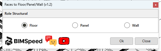
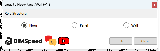
The three commands in BimSpeed.STR → Design create Analytical Panels. Floor in the command name does not mean a physical concrete floor. Each window contains Floor / Panel / Wall, Ok and Close.
Choose the input method
| Command | Revit selection | Result and limitation |
|---|---|---|
| Faces To Floor | Press Ok, pick geometric faces and Finish. | Uses edge loops from the faces. Start with a simple planar face without holes. Multiple loops require separate inspection because each is added to the creation list. |
| Lines To Floor | Press Ok, select Analytical Members, then Finish. Ordinary Detail Lines/Model Lines are not the required input. | Finds intersections, splits lines and detects a closed contour. Disconnected, incomplete or non-coplanar lines cannot form a valid panel. |
| Points To Floor | Press Ok, select Analytical Nodes (ReferencePoint) around the perimeter, then Finish. | Joins nodes in selection order and closes the last point to the first. Prepare at least four coplanar nodes; crossing the selection order creates a self-intersecting outline. |
Every option
| Control | Effect and verification |
|---|---|
| Floor | Assigns StructuralRoleFloor. Select the new panel and check Structural Role in Properties. |
| Panel | Assigns StructuralRolePanel. Does not create a physical wall or supply a complete design material definition. |
| Wall | Assigns StructuralRoleWall. Role and geometry are independent: selecting Wall does not rotate a horizontal contour vertically. |
| Ok | Hides the window for selection, then requests element creation in Revit. Finish ends selection; inspect any error message. |
| Close | Closes the window without deleting created panels. Use Revit Undo to reverse the generation transaction. |
Practice
- Prepare a rectangular floor face, four boundary Analytical Members or four perimeter Analytical Nodes, depending on the command.
- Run with Floor and inspect the new panel, contour and elevation.
- Use a different outline with Panel or Wall. Inspect Structural Role; changing role alone need not change panel count.
- Open a 3D view showing Analytical Panels, select a panel and inspect Properties. Save RVT and reopen it to confirm persistence.
Do not assume an opening was preserved because a face appears correct from a distance. Check the outer contour and Analytical Openings separately. Repeating the command on the same outline can add panels; inspect duplicates before proceeding.
Face/member/node selection needs verification for the command in use. A production handler supplied with a valid contour verifies panel writing; it does not establish the complete ribbon selection workflow.
Select inputs and recover from an empty result
For Faces, orient the view to expose the required face, press Ok, then select faces rather than whole objects. Start with a few faces and use Finish. For Lines, display Analytical Members; an ordinary drawing line coinciding with a slab edge is not a valid member. For Points, select nodes around the perimeter in sequence, not diagonally. After Esc or an incomplete boundary, read the message and prepare the inputs again. A returning window is not a generation report.
These three windows have no thickness, material or destination-elevation field. Geometry and elevation come from the selected boundary; Floor / Panel / Wall sets the role. Prepare vertical inputs for a vertical panel. To change panel dimensions, revise or reselect the boundary; changing role does not resize or thicken it.
Inspect and revise in Revit
Open a 3D view and enable Analytical Panels in Visibility/Graphics if required. Select the panel, read Structural Role in Properties, and inspect its contour and elevation in suitable plan/elevation views. Count newly created IDs separately from physical floors. For faces with holes, check for a solid panel inside the hole or overlapping panels; multiple loops do not establish that a proper opening was created.
If the boundary was wrong, Undo that creation and repeat with correct inputs. Close does not delete output. Check existing panels before repeating on the same area. Save the RVT, reopen a copy and inspect the panel's saved role and contour. These commands have no separate EDB export or RVT-save button.
The three role windows
Faces
Lines
Points
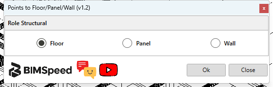
① Choose one Structural Role; ② Ok starts selection, Close dismisses the window. These are pre-creation UI states. Similar windows do not make their face/member/node selection workflows equivalent.
The bottom-left logo/Feedback/YouTube icons are explained under Design help buttons.