Lintels and wall editing
The steps and conditions below follow the current implementation. Runtime evidence is identified separately; availability of every command on the installed ribbon has not been verified.
Open BimSpeed.ARC → Model on a copy containing compound walls, openings and intersecting beams/columns. Compare Type, Location Line, Base/Top Constraint, offsets and thickness before and after each operation.
Create Lintel
This creates lintel beams, separately from Lintel Rebar. Open BimSpeed.ARC → Model → Create Lintel in a copy containing hosted doors/windows. Use a concrete Structural Framing family with b and h section parameters and openings the tool can read.
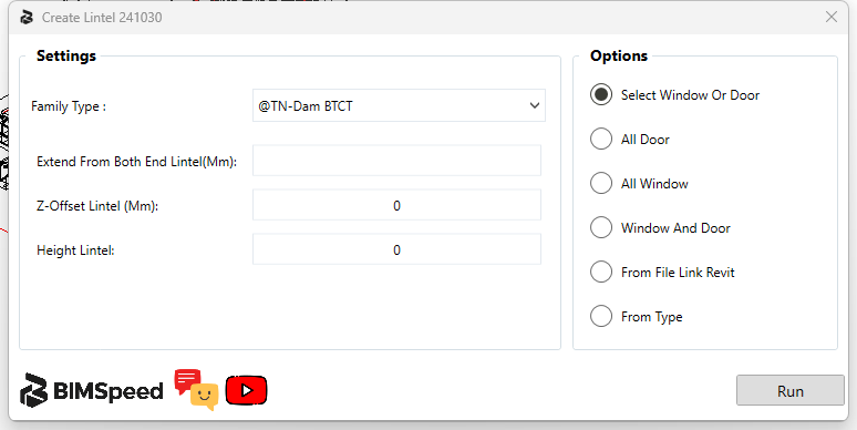
- Choose the concrete family in ① Family Type. In Create Lintel 241030, the tool finds/creates a type from the wall width at the opening and Height Lintel. This window has no separate Add Family Type button.
- Fill the three ② fields before Run. The image shows the initial state: empty end support and zero height; these are not successful generation inputs.
- Use ③ Select Window Or Door for one opening, then ④ Run and select it in Revit. Finish the selection. Whole-category modes use their full matching scope.
- Inspect the beam in elevation/3D: Type, Reference Level, Z Offset and measured length. Save the RVT after checking geometry. Editing settings does not automatically update existing beams.
| Field/mode | Unit, scope and effect | Verify |
|---|---|---|
| Family Type | Existing concrete framing family; not every framing family is suitable. | Generated b/h and unchanged shared types outside the intended output. |
| Extend From Both End Lintel (Mm) | Numeric mm at each end; increasing it extends both ends beyond the opening. | Actual length and bearing at both ends. |
| Z-Offset Lintel (Mm) | mm relative to the computed lintel position at the opening head; 0 is that computed datum. | Z Offset and section position above the opening. |
| Height Lintel | Section height in mm, for example 200. | Type h; this differs from door height and Z Offset. |
| Select Window Or Door | Pick a small source set. | Selected doors/windows, excluding walls/beams. |
| All Door / All Window / Window And Door | Matching instances in the current document. | Source instance count and individual failures. |
| From Type | Reveals category/type selection and uses matching instances only. | A type actually used by instances; type count is not instance count. |
| From File Link Revit | Select a link instance, then source/type and All Level or a single level. | Loaded link, transform and host elevations. The new lintel evidence does not verify this branch. |
| Run / X | Run creates elements; closing can retain settings. | Settings storage differs from RVT Save. A repeat run can add beams; it is not a proven same-ID update. |
Change end support and measure the result
A 900 mm instructional opening produced type 110×200. Each comparison was measured independently; only the 150 mm option remains in the demonstration model. An auxiliary educational door/wall was added because the original structural project had no doors; its concrete beam family came from the project. This verifies the production geometry helper, while ribbon picking/licensing remains unverified.
| Support at each end | Measured beam length |
|---|---|
| 75 mm | 1050 mm |
| 150 mm | 1200 mm |
| 300 mm | 1500 mm |
Changing 150 → 300 adds 300 mm across both ends. Changing to 75 removes 150 mm relative to the 150 option. Identify the newly generated beam after each run and keep or Undo that option; do not count overlapping comparison beams together.
Split Wall Layers
Run the command, select Walls and Finish. It reads Compound Structure, creates wall layers and changes the main wall type. The thickest layer receives main-wall handling, while other layers have opening-recreation logic. Check layer counts, materials, total thickness, interior/exterior direction, openings and door hosts. This is separate from Parts and splitting by level. Curved walls, hosted openings and equal-thickness layers still need runtime verification.
Cut Wall
① Select links model lists link instances with a selection checkbox per row when links exist. This captured window has no separate master “Revit Link” checkbox. An empty list provides no linked source for this operation.
- Load the required link and choose one instance. ② Selection component filters linked source categories: Column, Wall, Beam, Floor, Foundation, Stair and Generic Model. Disable unrelated categories.
- Press ③ Run. The window hides: select cutting elements in the link, Finish, then select target host Walls and Finish. These are separate selection passes.
- Inspect the modified wall profile/area at intersections, openings and unaffected portions. Touching bounding boxes do not prove a correct cut. Temporary copied cutters are removed; their originals remain in the link.
- Save the copy only after checking the result. Use the profile transaction group's Undo when appropriate; closing the dialog does not revert completed transactions.
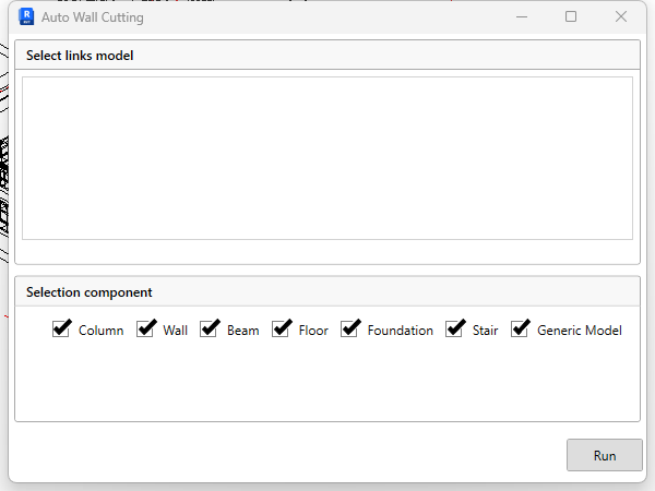
The captured Xhome link list was empty: it verifies the window/category controls, not Cut Wall output. Linked Formwork evidence does not verify this different cutting engine or picking workflow.
Split Wall
The entry opens the modeless SplitWallByElement2 window. Use Select Wall, then the appropriate tab:
| Tab | Controls and check |
|---|---|
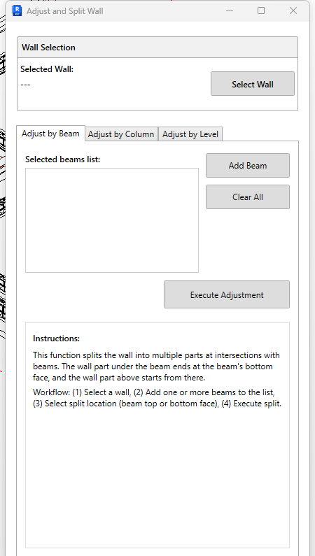
| Adjust by Beam | Add Beam, remove rows or Clear All; choose beam top/bottom, then Execute Adjustment. Check resulting wall elevations. |
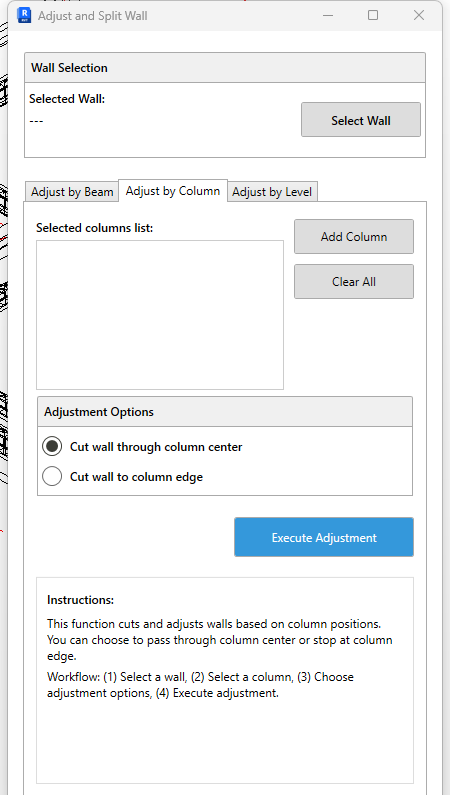
| Adjust by Column | Add Column, remove rows or Clear All; choose column centre/edge, then Execute Adjustment. Check segment counts and gaps. |
| Adjust by Level | Choose levels and Top/Base adjustment. Inspect constraints and offsets. |
Legacy XAML contains additional history/settings controls; those have not been established as controls in the current View2 entry. Modeless UI and saved output evidence remain incomplete.
Wall Location Line
The workflow repeats pick one wall → pick a reference-position point → continue or Esc. The command sets Location Line according to side and distance from the wall curve. Single-layer and compound walls may receive different centre references. Read the resulting Location Line in Properties; changing this reference does not prove that the wall moved to the clicked point. A new pick/Properties case remains pending.
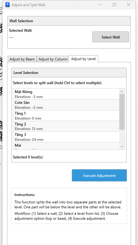
Split Wall View2: three observed tabs
These are actual English controls from Adjust and Split Wall. The Vietnamese Ready status is omitted from these unchanged crops; Vietnamese Level names are project data. Selected Wall = --- means no host was selected, not a successful split state.
- ① Select Wall picks one wall in Revit; verify its identity on return. ② chooses Beam, Column or Level rather than applying all branches together.
- For Beam, ③ Add Beam builds the cutter list; Clear All clears that prepared list. Once rows exist, check their top/bottom face choice and row removal before Execute Adjustment. Verify where the lower wall stops and the upper wall starts. An empty-list image does not verify those row-dependent choices.
- For Column, ① Add Column / Clear All manage cutter scope; added rows can be removed individually. ② Cut wall through column center and Cut wall to column edge use different geometric references. ③ Execute Adjustment runs the current branch. Inspect resulting segments, lengths and gaps at columns; save separately for comparison.
- For Level, use Ctrl to select one or more levels in ①, check Selected n Level(s), then ③ Execute Adjustment. ② Elevation labels have a unit defect: Mặt Móng displays −3mm but its native Elevation is −1000mm; Tầng2 displays 13mm versus an actual 3850mm. This build rounds internal feet and labels them mm. Select by name/ID and check Level Properties; do not use the displayed mm values as elevations. Inspect wall Base/Top Constraints, offsets and actual elevations after splitting. A blue button with an empty list does not establish valid inputs. These UI screenshots do not verify a saved Split Wall output.