Auto Land Boundary — point coordinates, Excel and boundaries
Open BimSpeed.ARC → Utilities → Auto Land Boundary; it may also appear in STR Common. Prepare a plan and ordered boundary points. Entered-coordinate geometry does not establish the correct survey coordinate system.
| Control | Input and effect |
|---|---|
| Add Point / Delete | Adds/removes a point row. Row order defines edge connectivity, so deleting a row can change the boundary. |
| Point Number | Point identifier used for marker information, not a distance. |
| X / Y / Z | Metres, converted internally during creation. The reviewed text reader removes commas; do not use a comma as a decimal separator. Check imported values and a known distance. |
| Create by Floor / Floor Type | Creates a Floor region with the chosen type; inspect its thickness/material. |
| Create by Detail Line / Line Style | Creates view-specific detail lines, not a 3D floor or legal Revit Property Line. |
| Place reference points / Type | Creates markers using the selected family/type when enabled. Use Load Family if unavailable. |
| Import Excel | The reviewed version reads AutoLandBoundaryTemplate.xlsx from its template folder, then extracts/opens the template again. Do not assume an arbitrary-file picker. Keep the source coordinate table separately and compare row count, ordering and values before Run. |
| Load Family | Loads marker content; it does not validate coordinates. |
| Run | Creates boundaries/markers from the current choices. |
Floor elevation: check Level, Height Offset and Elevation at Top together after Run. In the reviewed Revit 2024 case, input Z −1.000 m produced a Floor top at −2.000 m. Read the measured values and verification scope below before using the result.
Use at least three non-collinear points without duplicate adjacent points or self-intersections. The reviewed Detail Line branch joins the final point back to the first at the first point's Z; varying row Z values do not produce a general 3D polyline. Measure an edge, inspect Floor area where applicable, and review marker BS_SURVEY_POINT_X/Y/Z fields if supported.
Check Base Points before/after: the reviewed execution path can unpin the Project Base Point and Survey Point, then write the Project Base Point E/W and N/S parameters from the first point's X/Y, with Elevation=0. Test only on a copy and record initial values/pinning. Do not treat it as a detail-line-only command with no coordinate-origin side effects.
Shift one X by 1 m in a copy to inspect the effect, then Undo. Reordering points can self-intersect the boundary. Repeated Run can add output; inspect/remove only prior output or Undo before repeating. Save and reopen the RVT separately from the Excel input.
Observed Revit images
Floor-generation output and data after reopening a Revit 2024 project copy. Captions distinguish full-interface captures from native view exports. Ribbon entry, point-entry UI and Excel were not exercised. Click an image for the original at full resolution.
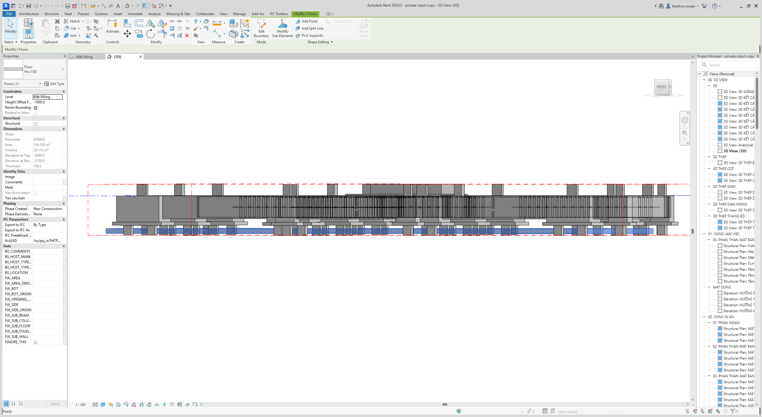
Revit 2024.3 on the reopened project copy: Floor ID 9247650 was read back after saving, without rerunning generation.
- The selected Hs=150 Floor reads 134.100 m² area, 20.115 m³ volume and 150 mm thickness. Level/Height Offset −1000 mm give Top −2000 and Bottom −2150 mm; read the elevation warning.
- The new Floor is highlighted blue below the existing grey project geometry. This is the FRONT orientation of a 3D view, not a perspective.
Native export from the FRONT-oriented 3D view

Geometry exported directly from the same Revit view; the lower blue band is the selected Floor. This is a native view export, not a full-interface screenshot. Grey geometry is pre-existing project content.
Coordinate workbook
Download the bundled Auto Land Boundary workbook. This is the unchanged tool resource. Columns A–D contain point number, X, Y and Z; reading starts on row 2 and stops at an empty A cell. Coordinates are metres. Keep a separate source copy and validate your values before Run; sample coordinates do not establish a project's legal boundary.
Observed build and verification scope
The production Floor-generation service was checked on a Revit 2024 project copy, then the saved result was reopened in a fresh Revit process and the recorded ID read back. The input was a 14.9 × 9.0 m instructional rectangle derived from an existing floor bounding box, not a project cadastral boundary. New Floor ID 9247650, type Hs=150, area 134.10 m², volume 20.115 m³ and thickness 150 mm persisted after reopening. This did not exercise the ribbon entry, Excel/input UI, Detail Line or point-family branches.
| Point | X (m) | Y (m) | Z (m) |
|---|---|---|---|
| DOCS-1 | -1.11 | -0.11 | -1.00 |
| DOCS-2 | 13.79 | -0.11 | -1.00 |
| DOCS-3 | 13.79 | 8.89 | -1.00 |
| DOCS-4 | -1.11 | 8.89 | -1.00 |
Check elevation separately: the input Z was −1.000 m, but the reopened Floor had a −1.000 m level, Height Offset = −1.000 m, Elevation at Top = −2.000 m and Bottom = −2.150 m. Input Z was therefore not validated as the desired top elevation. Check the level, height offset, top/bottom elevations and Base Points before using the result. Correct the project copy to the design elevation and verify again after saving/reopening.